1

I've got an analog signal that's only 0.00076317235 V. It comes from an IR sensor, and I'd like to read it with an Arduino by amplifying it to 3 V (or 4000 times.)

I am a novice at electronics. I have LM324Vs at hand and I can also use an ADS1115 16-bit ADC, if necessary.

Can someone suggest an amplification circuit (or a ready-made module)?

enter image description here

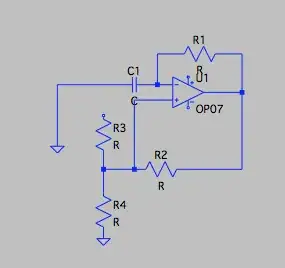
How about in the above replacing R2 by 20M resistor which should give it a gain of 2000 times and using the other transistor in LM358 with a 10K at R2 to gain 2 times which should take the net to 4000 times? Of course I'll be supplying Arduino 5V to the LM358, not the 10V as shown in the image.
enter image description here

enter image description here

  • https://en.wikipedia.org/wiki/Instrumentation_amplifier Although just a standard negative feedback solo op-amp may also work. – horta Nov 22 '22 at 07:32
  • https://en.wikipedia.org/wiki/Operational_amplifier#Negative-feedback_applications – horta Nov 22 '22 at 07:35
  • @horta thanks for the links, I have given them a cursory read, I think I'll be needing a non-inverting amplifier, but could you help with a ready made circuit somewhere which saves me the task of having to design it from scratch? All the maths might be too difficult for me. – Lord Voldemort Nov 22 '22 at 07:39
  • Measuring with precision upto 8 digits on Arduino is problematic. 10bit ADC will allow you to read at most 3 digits. With such a low precision ordinary operational amplifier should do it job. – ufok Nov 22 '22 at 07:43
  • @ufok I could place a 16 bit adc module in the path which is read by arduino through I2C connection, so that's not an issue, I just need to amplify my signal 4000 times first. So maybe use a LM358? – Lord Voldemort Nov 22 '22 at 07:54
  • Before posting an answer we need some details about where that signal comes from *(datasheet, part numbers, anything useful)* and what your precision requirement is. With an Arduino it may not be possible to take "that precise" measurements. – Rohat Kılıç Nov 22 '22 at 07:59
  • @RohatKılıç the signal is coming from an IR sensor https://robu.in/wp-content/uploads/2022/04/Infrared-Reflective-Sensor-UserManual.pdf , as precise as possible, and I can use a ADS1115 adc (16Bit) if arduino adc is insufficient. I'd like to use a LMV324 op amp to amplify this as I already have it. Thanks – Lord Voldemort Nov 22 '22 at 08:06
  • The manual indicates it can be directly connected to MCU. What special usage would need amplification by 4000 ? – Justme Nov 22 '22 at 08:09
  • @Justme it is currently directly connected to the Arduino, the base signal I am getting is 0.3V or 62 ADC. I am expecting a voltage fluctuation of 0.00076317235 V which Arduino will not be able to see, hence my quest for amplification to take it up to 3V – Lord Voldemort Nov 22 '22 at 08:14
  • 6
    Why are you expecting such a weak signal on the analog output of the module? The module is intended for use as a detector - it has a digital output that tells you when the reflected IR is above a particular level. The analog output seems to be just the raw signal from the phototransistor. – JRE Nov 22 '22 at 08:19
  • @JRE that's the application, and that's why I am using the analog output. I am pointing this sensor to a surface where a very slight pulse is expected to pass. Its so slight, that I need that sensitivity to pick that tiniest of bulges forming. – Lord Voldemort Nov 22 '22 at 08:21
  • How fast do you expect the signal to change? – Bruce Abbott Nov 22 '22 at 08:26
  • 3
    @LordVoldemort Have you considered it is a wrong sensor for the job? You don't know the internals of the module so you might be better off designing a photodetector yourself, than amplifying the output of a mystery sensor with mystery sensitivity and bandwith? – Justme Nov 22 '22 at 08:30
  • 1
    Did you measure the pulse with an oscilloscope or something? I find that precise voltage you've named to be rather excessively exact. – JRE Nov 22 '22 at 08:34
  • @BruceAbbott frequency should be 300-500, – Lord Voldemort Nov 22 '22 at 08:51
  • @Justme you've just given me the idea, maybe I should look into that, was trying to escape the hardwork. Does it matter what the internal workings of the sensor are if its giving an analog output? – Lord Voldemort Nov 22 '22 at 08:52
  • @JRE its just a big wild hunch (but poorly educated, yet still educated hunch). – Lord Voldemort Nov 22 '22 at 08:52
  • @LordVoldemort Yes, of course it matters. If you don't know sensitivity and bandwidth of the sensor, you don't know how weak and fast pulses it can detect. – Justme Nov 22 '22 at 09:01
  • 1
    @Justme please guide me how to build a high sensitivity IR sensor that could detect my signal. – Lord Voldemort Nov 22 '22 at 09:03
  • You can make a current-to-voltage amplifier by passing a current into the base of a transistor, which has a large resistor on its collector. Additional design effort is needed to "bias" the transistor so that it's neither fully turned on, nor fully turned off, all of the time. – user253751 Nov 22 '22 at 09:27
  • Please view my question edit, my simple head looking for simple solutions has found an op-amp application for 4000 gain. Could it work? – Lord Voldemort Nov 22 '22 at 09:58
  • Probably ok (not in one stage ... I should use 3 stages 20x-20x-10x, frequency to be known) for AC signals, not for DC. – Antonio51 Nov 22 '22 at 10:08
  • @Antonio51 Why not for dc? my signal is dc. I thought this circuit was for dc. – Lord Voldemort Nov 22 '22 at 10:38
  • 1
    Offsets will be very very difficult to solve with such gain ... However, if we don't know the exact specifications of your DC signal ... and of your circuit board, that's quasi "impossible". – Antonio51 Nov 22 '22 at 11:06
  • 2
    You should tell us EVERYTHING technical that you know about the requirement. Your notes make it apparent that you have a module with an LM393 comparator. Probably similar to [this](https://www.waveshare.com/wiki/Infrared_Reflective_Sensor) application for a Raspberry Pi. If you tell us what you have and what you are actually trying to do we can probably help. As it is you are not really asking the right question. What are you trying to achieve at the top level?. – Russell McMahon Nov 22 '22 at 11:14
  • 1
    @LordVoldemort OP is talking about "voltage fluctuation of 0.00076317235 V" - it's 8 DECIMAL digits ~= 27 binary digits. I am convinced that 27 bit measurements are way to hard to accomplish properly for someone not familiar with opamp idea. – ufok Nov 22 '22 at 13:25

2 Answers2

2

In the comments you say,

the base signal I am getting is 0.3V or 62 ADC. I am expecting a voltage fluctuation of 0.00076317235 V

and,

I am pointing this sensor to a surface where a very slight pulse is expected to pass... frequency should be 300-500,

While it is quite possible to amplify a voltage of ~0.7 mV using a low drift op amp, the 'base' level of 0.3 V could be a problem because it may vary a lot more than the signal.

If you are only interested in the 'bumps' then it might be better to use an AC amplifier that cuts off frequencies below 300 Hz so the 'base' voltage is removed. This will also filter out low frequency noise, and the LM324V's relatively high drift will not be a problem.

Bruce Abbott
  • 55,540
  • 1
  • 47
  • 89
  • Aha...I think this should be useful and achievable within my limited electronics knowledge. So I was already planning to use a LM324 to amplify this and use all four of its transistors for the same, I was planning to use this circuit https://xtronic.org/circuit/amplifier/operational-amplifier-video-tutorial-and-super-microphone-circuit-with-lm324/ . How would the AC amplifier take shape? WHat modification should I do to it? – Lord Voldemort Nov 23 '22 at 03:36
0

How to amplify an analog signal 4000 times?

If you want to measure something at such levels,
you should use a "synchronous" amplifier and demodulator ...
So, you need to supply the sensor with a AM PWM voltage ... or FM.
NB: be aware that for such a gain (4000), it would not be an easy task.

However, this should help. AC Analysis

enter image description here

TRAN Analysis

enter image description here

From this, the principle of AM modulation and demodulation.
Note that for FM modulated signal, you need a FM demodulator or PLL.

AM modulation and demodulation

Theoretical background AM)

enter image description here

Example of a synchronous AM modulator and demodulator.

enter image description here

FM modulation and demodulation

enter image description here

enter image description here

From Symetrix ... PLL HC4046

enter image description here

Antonio51
  • 11,004
  • 1
  • 7
  • 20
  • 1
    So I supply the sensor with PWM voltage, and use Synchronous amplifier and demodulator? Can you please elaborate for someone new to electronics what is a synchronous amplifier and how to go about it? – Lord Voldemort Nov 22 '22 at 09:19
  • Thanks for the elaborations. Will need to study it and if need more clarification I will come back. – Lord Voldemort Nov 22 '22 at 09:59
  • 1
    That's about a 1 mV signal. It needs better than an LM358, but I suggest it probably doesn't need anything as fancy as you are propopsing. – Russell McMahon Nov 22 '22 at 11:02
  • Right. But without exact specs, I choose a common frequency where my old op-amp can work easily. NB: noise would be "probably" high level. Did not simulate. That is why I proposed a "synchronous" amplifier. I did not propose an amplifier version with "random" noise added ... with a correlator detection ... – Antonio51 Nov 22 '22 at 11:09