dismantling some of your writing
You've already got some useful answers. And I certainly don't intend on muddling things further. I just have a slightly different slant to offer.
Let's start here:
I am learning about ideal op-amps. One of the main characteristics of
this device is the infinite open loop gain, which means that we can
deduce that the 2 input voltages are the same as v2−v1=v3A=0
because the gain is ideally infinite.
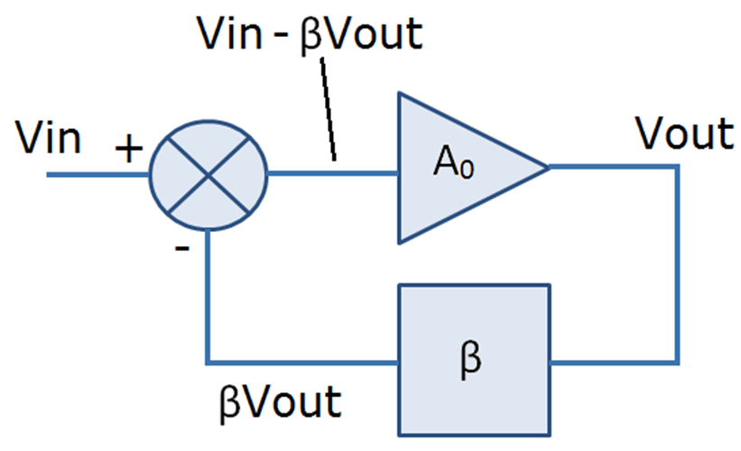
There's an assumption buried in the above that I want to haul out into plain view. Perhaps the best way to do that is to just draw this ideal opamp:
simulate this circuit – Schematic created using CircuitLab
There's nothing there to cause \$V_{( - )}=V_{( + )}\$. They are independent of each other at this point. We could set \$V_{( - )}=+2\:\text{V}\$ and \$V_{( + )}=-1\:\text{V}\$. That may leave us with a bit of an difficult situation considering \$V_{_\text{OUT}}\$ as it implies multiplying a finite difference by infinity. But that detail doesn't force the two inputs to be the same.
The point to make here is that it is only with the addition of feedback from the output that we can arrange things so that \$V_{( - )}=V_{( + )}\$. So there was something implied in your writing -- feedback -- that you may or may not have been thinking about when writing. I just want to make sure to call it out to your attention so that it doesn't slip under some rug.
This is a deduction we can make because we also assume the op amp is
generating a finite output signal, but why can we assume this?
When premises are false, even valid logic cannot rescue the conclusion. So This is just wrong. We don't assume the inputs are the same. In fact, it would be very easy for me to show you a circuit where the opamp is nearly ideal and yet the inputs are different by more than a few volts. This can be due to a design error but it is also fairly common in good designs where the device is operated as a comparator. So, no. We don't assume it. We prove it, when appropriate, as an output result taken from true axioms and valid logic leading to soundly reasoned conclusions.
It seems like we are making a backwards deduction, as in we know the
gain is infinite, and thus the deduction is the output signal is also
infinite, but if the output signal is finite the only reason this can
be is because the two input voltages are the same, however this
deduction is based on the assumption that the output signal is finite.
Why can we assume this? In real life, the open loop gain will be very
large but not infinite. Why can we assume the output signal will be a
"normal" signal and not massively amplified?
So, by now, you've gone down the rabbit hole because you started with some incorrect assumptions. Given those, I can see why you imagine some kind of circular logic. But that's definitely not the case.
inside a bipolar (BJT) opamp
Before finishing up by solving for an analog amplifier stage with voltage gain, I'd like to take a quick break from the above. Kind of an intermission of sorts.
Let's take a moment and just observe something about the input stage that's inside a bipolar (BJT) opamp. It's usually related to what may be called a differential pair of BJTs. Without belaboring the details, the idea is that the emitters of the two BJTs are tied together and given a kite tail of sorts which is an ideal (hypothetically, but not really) current source/sink. (Together, the two BJTs plus the 'kite tail' current source/sink is called a long-tailed pair.) If the bases of the two BJTs are exactly equal, then their collectors will exactly split that current in half, each taking up \$\frac12\$ of the tail current. But if there's so much as a slight difference, then more of the current will go one direction than the other. It's kind of like a water valve which can split the flow of water into two different hoses/pipes, but where you can control the diversion.
As it turns out, this only works within a small difference range. If the voltage difference (BJT input opamp) exceeds \$200\:\text{mV}\$ then the entire flow is directed one way and not the other. And any further difference isn't going to change anything. In effect, the ability to continue applying some hypothetical voltage gain has been destroyed.
So real opamps have a narrow range within which their input differences are multiplied (approximately) by some assumed, fixed voltage gain. And it is a pretty narrow range. So a good design (excepting comparators, for example) will arrange things so that both inputs are arbitrarily close, but not exactly the same.
You need to keep this also in mind. (Also, opamps will often protect their inputs so that the difference cannot be too excessive, by just internally dumping current and loading down your source a lot when you exceed some small range of allowed difference. Diode protection is one way to do this.)
Now we can look at an analog amplifier stage with voltage gain.
opamp with feedback and finite voltage gain
simulate this circuit
Here, we want to assume that both inputs are identical. And since we know \$V_{( + )}=0\:\text{V}\$, then that means \$V_{( - )}=0\:\text{V}\$. But how do we know that? Well, we don't because it's not really true. We just know that the difference will probably be very small.
But you need to work through that, rather than assume it. So let's not assume it. Let's prove it.
As \$V_{_\text{OUT}}=A\cdot\left(V_{( + )}-V_{( - )}\right)\$ and \$V_{( + )}=0\:\text{V}\$ then \$V_{_\text{OUT}}=-A\cdot V_{( - )}\$. But this output drives one side of a resistor divider with the other end at \$V_{_\text{IN}}\$. So the midpoint of the divider will be \$V_{( - )}=\frac{V_{_\text{IN}}\cdot R_{_\text{F}} + V_{_\text{OUT}}\cdot R_{_\text{IN}}}{R_{_\text{IN}}+R_{_\text{F}}}\$.
As we already know that \$V_{( - )}=-\frac{V_{_\text{OUT}}}{A}\$, find \$V_{_\text{OUT}}=-V_{_\text{IN}}\cdot\left[\frac1{\left(1+\frac1{A}\right)\cdot \frac{R_{_\text{IN}}}{R_{_\text{F}}}+\frac1{A}}\right]=-A\cdot V_{( - )}\$.
Or, that \$V_{( - )}=-\frac{V_{_\text{IN}}}{A}\cdot\left[\frac1{\left(1+\frac1{A}\right)\cdot \frac{R_{_\text{IN}}}{R_{_\text{F}}}+\frac1{A}}\right]\$.
Now, pause for a moment.
You should be able to see easily now that as \$A\to\infty\$ then \$V_{( - )}\to 0\:\text{V}\$ and \$V_{_\text{OUT}}\to -V_{_\text{IN}}\cdot\frac{R_{_\text{F}}}{R_{_\text{IN}}}\$.
So it's not assumed. If you are willing to take \$A\to\infty\$ then it is proved.
(Note that it is proved only assuming the circuit I provided, which has feedback from the output backwards to one of the inputs. If that wasn't present, then the results would of course be different.)
If you are a designer using practical opamps then you will be aware that \$A\ne\infty\$ and then of course there will be a small difference between the inputs. But this fact that the difference is small is as a result of feedback in this particular schematic, which allows the extremely high open loop opamp voltage gain to operate on the inputs.
You are, in fact, encouraged to use any particular value for \$A\$ to see where that takes you in this case. Try out 10, 100, 1000, etc. See what happens. It's useful to go through the exercise.