2

Switching on a relay is simple: just power it. Switching it off can be another matter.

What is the fastest way? (Yes, relays are slow by electronic standards, but we can still try to make them as fast as possible.)

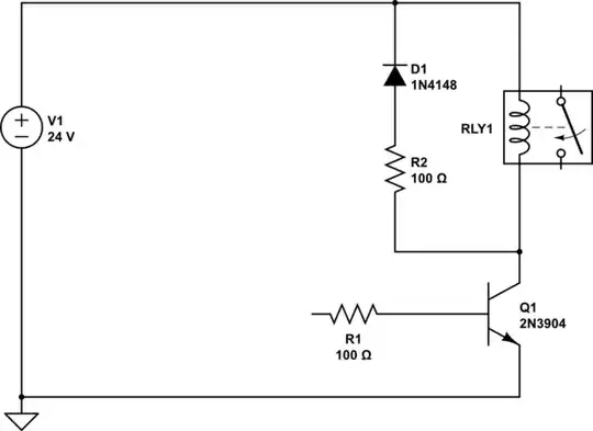
In most cases I just insert a free wheeling diode:

schematic

simulate this circuit – Schematic created using CircuitLab

This gets rid of the energy in the coil over time. Because the diode only drops about 0.7V, I mostly have the resistance of the coil to dissipate the energy. This is not ideal since the current is slowly reduced which will make it somewhat difficult to predict when the relays will really switch off (and in the worst case might even lead to more abrasion the the contacts of the switch if they are under load.)

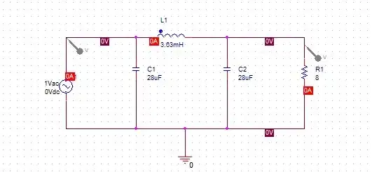
Now I could put a resistor in series to the diode:

schematic

simulate this circuit

I'll have to select the resistor so that at the rated current of the relay coil Vcc + +VD1 VR2 is smaller than the breakdown voltage of Q1.

Something that seems to be included in dedicated driver circuits. Some sort of Zener diode or other voltage limiting circuit.

schematic

simulate this circuit

What's the fastest clean way to switch of a relay or other magnetic? What are the benefits and downsides like EMI, energy consumption, etc.?

JRE
  • 67,678
  • 8
  • 104
  • 179
kruemi
  • 2,994
  • 16
  • 29
  • 2
    You want to apply the maximum possible reverse voltage until the current stops. I'd experiment with a Zener freewheeling diode, vs your last circuit. Whichever one delivers more reverse voltage over time is probably the winner. The freewheeling Zener could get to higher peak voltages, but passing the current through the power supply could deliver a consistently high voltage for longer. P.S. Make sure it doesn't break the power supply. – user253751 Nov 15 '22 at 12:07
  • 1
    Put the zener in series with the freewheeling diode, anode to anode. This will effectively increase the forward drop of the diode without introducing any other adverse effects. – Dave Tweed Nov 15 '22 at 12:17
  • 1
    Do keep the power dissipation of these components in mind if the device can ever switch on and off quickly many times. Might find that some watts are dissipated for some milliseconds, which is fine at 0.1% duty cycle, but becomes magic-smoke-releasing at 10% duty cycle (especially when including highest possible ambient temperature.) – rdtsc Nov 15 '22 at 13:04
  • @DaveTweed I thought about that but than thought that a resistor of same power value is cheaper. But true, the Zener keeps the voltage drop high while with the resistor the voltage drop will go lower linearly with the current thus reducing the disappiated energy per time (power) in the square... – kruemi Nov 15 '22 at 14:38
  • Yes, that's the difference. This topic has [come up before](https://electronics.stackexchange.com/q/235072/11683). Also [here](https://electronics.stackexchange.com/q/115857/11683). – Dave Tweed Nov 15 '22 at 15:08
  • And more recently [here](https://electronics.stackexchange.com/q/467294/11683). Did none of these pop up when you were writing your question? The system is usually fairly good at finding similar questions that already have answers. – Dave Tweed Nov 15 '22 at 15:17
  • @DaveTweed oh.. seems I was looking for the wrong words when I searched for an answer on here... Feel free to mark this as a duplicate than. – kruemi Nov 16 '22 at 05:42

2 Answers2

3

Here's how the zener alone works. I modeled the relay as an inductor of 100 mH with a series resistance of 240 Ω so that the steady-state current is 100 mA.

schematic

simulate this circuit – Schematic created using CircuitLab

If you run the simulation, you'll see that the current drops to zero in about 50 µs. However, note that when switching on, it takes about 680 µs for the current to rise to 80% of its peak value.

What if you also care about how quickly the relay turns on? Here's a thought I had: Why not store the energy in a capacitor and use it to speed up the current rise at switch-on time. It took a bit of work to come up with a workable circuit — I had to add a transistor that switches on only when its emitter is driven below ground by the capacitor. When the driver transistor switches on, the charge on the capacitor drives Vc strongly negative, increasing the rate at which the current in the coil rises.

schematic

simulate this circuit

You can choose the capacitor value based on the energy stored in the coil and how high you want the voltage to rise at Q1's collector.1 This particular value gives the same 200 V peak as the zener above.

It does work, at least in simulation (I haven't tried to build it). The current fall time is a little longer at 83 µs, but the current rise time (to 80%) is decreased to just 60 µs. And note that the coil's stored energy isn't dissipated, eliminating that source of waste heat.

Of course, in a real application, the effectiveness of this circuit would depend on the length of time that the relay is off. If it's too long, the charge on C1 will leak away before it can be used.


1 It's a simple matter of energy transfer. The energy in the coil is \$\frac{1}{2}L I^2\$ while the energy in the capacitor will be \$\frac{1}{2}C V^2\$. We can set these equal to each other and solve for C, giving:

$$\frac{1}{2}C V^2 = \frac{1}{2}L I^2$$

$$C = L \frac{I^2}{V^2}$$

Plugging in our known values (L = 100 mH, I = 100 mA, V = 200 V) gives us the value 25 nF.

This works for an ideal inductance, but a real relay will require some experimentation, since it is non-ideal in several significant ways.

Dave Tweed
  • 168,369
  • 17
  • 228
  • 393
  • Oh, that's a nice one...I do a bit of the opposite (with quite beefy valves at 24V) to reduce the heat they emit when switched on for extended periods of time. I put a resistor in series and a capacitor parallel to that resistor. So I get the full 24V to open the Valve but the series resistance takes up about halve the voltage in steady state thus reducing the current by 50%. So I have 25% of the heat on the valve (and an additional 25% on the series resistor). If I took a 12V Valve in such a config I could probably speed it up a bit as well :) – kruemi Nov 17 '22 at 05:46
2

You can keep npn bjt but use a higher volt part like say 300V.Then a 200 Volt zener and no Freewheel diode will help speed.

Autistic
  • 14,235
  • 2
  • 27
  • 65
  • 1
    Thank you... That makes sense. High voltage (at same current) means higher power which will help get rid of the energy faster. Will the sudden spike to 200V have negative effects regarding EMI tough? – kruemi Nov 16 '22 at 05:39
  • 1
    @kruemi Sudden sharp spikes can sting sensitive electronics .Small relay coils have lots of parasitic capacitance which limits rate of rise of voltage at turnoff and not much energy .You should be fine . – Autistic Nov 16 '22 at 08:50
  • Consider using an avalanche rated power MOSFET. When reverse biased it will behave like a resistor approximately 2X its RDSon. any data sheets now give you the amount of energy they will adsorb. Do not forget to take this heat into consideration when doing thermal calculations. Also turning it off faster will also help, do this with a low impedance gate circuit. – Gil Nov 17 '22 at 04:08