8

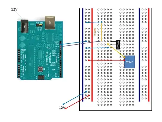
I've connected an Arduino to a MOSFET to control a valve.

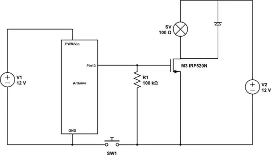
I've connected the Arduino's GND to the negative lane (word?) on the breadboard (for clarity modeled by SW1 in the circuit diagram). I noticed that if I don't do this, it does not work (no voltage at the gate) - why do I need to use the same ground?

And: Is my circuit any good or could it be damaging my Arduino?

See sketch here

schematic

simulate this circuit – Schematic created using CircuitLab

jippie
  • 33,033
  • 16
  • 93
  • 160
PhilW
  • 215
  • 2
  • 7
  • I tidied your circuit diagram a bit so it is easier to read. I attempted to make it identical to the Fritzing image. I modeled the GND connection between Arduino and breadboard by SW1 as this is the main topic of your question. http://electronics.stackexchange.com/questions/28251/rules-and-guidelines-for-drawing-good-schematics – jippie Apr 03 '13 at 15:57

2 Answers2

12

Voltage is a potential relative to a point. In electronics, most of the time that point is circuit common, or ground. When the grounds aren't shared, there is no reference, so the 5V coming from the Arduino is meaningless.

Another thing, put the common lead of the power supply as close as possible to MOSFET return path, ideally in the pin next to it. That will keep the return current off your ground bus, and that is known to make microcontrollers behave in undesirable ways. It may not be a problem for this circuit since its only 120mA, but it's a good habit.

Matt Young
  • 13,734
  • 5
  • 34
  • 61
  • Thank you! So the rule is: always use one common ground? (for basic stuff like this, anyway - I suppose the more I understand the clearer this will become) Also, the thing about the positioning the lead next to the mosfet, is this in any way related to the diode that Botnic would place to the valve? (return current vs voltage peaks?) – PhilW Apr 03 '13 at 16:22
  • 1
    You always need to have a common ground, regardless. More complex circuits may be a power, analog, and digital ground. The grounds are separated for noise immunity, but they are tied back together at the power supply. That is where the lead position comes in. The flyback suppression diode is always a good idea, however, Botnic's schematic has the diode backwards. – Matt Young Apr 03 '13 at 16:56
1

It seams strange to me to connect the Gate to a constant 5V pin. Shoudn't this be on a IO-pin?

I would add a diode to the valve in order to prevent voltage peaks when turning the FET off. enter image description here

Botnic
  • 2,245
  • 2
  • 19
  • 33
  • Sorry if this was not clear - yes, it's a digital output pin that supplies 5V (HIGH). Thanks for the diode idea! I've only read about it but wasn't able to put it to use so far. – PhilW Apr 03 '13 at 16:18
  • 2
    That diode is shorting the valve. Don't do that. – Matt Young Apr 03 '13 at 16:55
  • 1
    Oh yes your right, I correct that. Ok now the Diode is in the right direction. – Botnic Apr 04 '13 at 06:36
  • _While this is a useful note, it does not answer the question_. You should've commented instead. –  Apr 04 '13 at 06:46