13

I've made a Joule Thief, and it works fairly well, but not as well as I would like.

enter image description here

It's powering a 3.2v LED from a 1.2v battery, but it's very dim. I'm hoping that increasing the voltage from the JT will improve it, but I'm not sure how to increase the duty cycle of the transistor. In fact, I'm not actually sure what's making the transistor turn OFF - apparently, the toroid core saturates and somehow switches it off, but I don't really understand WHY that would happen.

I've also tried the "supercharged" version that's apparently almost 30% more efficient, but the only difference seems to be that the LED is dimmer.

enter image description here

From http://rustybolt.info/wordpress/?p=221

Voltage Spike
  • 75,799
  • 36
  • 80
  • 208
Alex Freeman
  • 557
  • 1
  • 8
  • 20
  • 1
    What is the duty cycle you are seeing? Can you post the circuit? Are you the guy asking about this a week or so ago? – Andy aka Apr 03 '13 at 14:25
  • 1
    Please add a circuit diagram of both situations, we can't help you without. – jippie Apr 03 '13 at 14:28
  • Last Joule Thief circuit I saw on here was not at the top of the list when one searches for 'Joule Thief', so here it is. Maybe what Alex is using, maybe not. Alex??http://electronics.stackexchange.com/q/63873/15779 – Bobbi Bennett Apr 03 '13 at 15:02
  • 1
    Post the schematic of exactly what you built. There are lots of variants out there. Without knowing the specific circuit, there is not much that can be said. – Olin Lathrop Apr 03 '13 at 16:03
  • http://rustybolt.info/wordpress/wp-content/uploads/2011/12/JT-ConvSuperchgd2.gif contains both the conventional and supercharged versions - the switch on the schematic allows you to change between them. fyi I built each one in turn (i.e. I didn't build it with the switch, only one circuit existed at the time). I can't tell what the duty cycle is. I estimate it to be above 0.5, maybe 0.6 or so, since i'm producing enough to just about light the led from a battery about 1/3 its voltage. However, I don't know exactly what the output voltage is, and my ammeter's broken. And I'm not the same guy. – Alex Freeman Apr 03 '13 at 16:07
  • 1
    Do you have a picture of the circuit you actually built? – jippie Apr 03 '13 at 16:12
  • Well, not exactly. In order to make rearranging easy I connect the components via crocodile clips, but I've mostly dismantled it. But it's almost exactly the same circuit. I've had to improvise a little - lacking resistors to hand, I put two 3.3kOhm in parallel to make 1.6kOhm resistance, which I used in place of the 1.5kOhm OR the 1kOhm. I could assemble it now and take a picture if it really helps. – Alex Freeman Apr 03 '13 at 16:21
  • 2
    That's a pretty crappy circuit as it depends too much on unpredictable things like the actual parameters of the transistor. However, try putting 100 nF or maybe 1 uF cap to ground on the right side of R1. That should allows the pulses into the base to have more amplitude. What frequency is this switching at? – Olin Lathrop Apr 03 '13 at 18:27
  • 3
    If anyone's reading this, I found another article on rustybolt that explains the proper dynamics really well. Also clarifies that the wikipedia article isn't brilliant. http://rustybolt.info/wordpress/?p=134 Thanks for your help guys. – Alex Freeman Apr 04 '13 at 01:41
  • @AlexFreeman consider answering your own question and accepting your own answer. – Phil Frost Aug 17 '13 at 19:27
  • 1
    As posted in comments the answer was found with [Joule Thief Coil Explained](http://rustybolt.info/wordpress/?p=134). That explains all the things that you have consider to build a Joule Thief circuit, from the coils to the wiring. – Butzke Oct 02 '13 at 18:32
  • [Meta Discussion on this Question](http://meta.stackexchange.com/questions/237198/its-my-schematic) – Justine Krejcha Jul 27 '14 at 17:36
  • You should have mentioned all the "parameters" for your particular circuit, especially the coupled-inductor (transformer) and its resistance (and inductance, if possible). Also, the frequency of operation is helpful, as well as a picture of it, and as detailed specs as possible on every component -- LED, battery type & operating voltage, resistor value, transistor, circuit layout, magnetic material type, # of turns, wire used, switch type, LED string layout if relevant. And also any parasitics you might suspect are robbing the brightness. Try using a fresh AA, and reducing the resistance. – MicroservicesOnDDD Jan 09 '22 at 21:04

2 Answers2

9

This one's a year old, but I'll necro it because I think I can say something useful.

Joule Thief circuits got a bad rap some time ago because some people in the over-unity, free-energy crowd went nuts over it, so lots of people won't really spend any time talking about it. Turns out, you still can't get something for nothing. So, moving on.

Pretend for a moment, the battery in the moment isn't connected. No current, no voltage anywhere else in the circuit. That's our starting point.

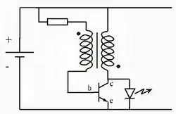
When the battery is first connected, the only path for current to really flow is into the base of the transistor. As the transistor gets biased, the current from the collector to the emitter will rapidly increase as a multiple of the current flowing into the base, depending on the exact transistor used. The increasing current will start to store energy in the secondary winding, just like any other inductor.

See those dots are the top and bottom of the transformer? A current flowing into the top of the coil on the left, will turn into a current flowing out from the bottom of the coil on the right. This current won't particularly be able to drive the LED, so its going through the transistor.

What happens next is a little bit hard to explain. The easiest way to explain it is to follow those dots. The current that is now flowing from top to bottom on both sides of the transformer generates opposite polarities of voltage from each other. And the current on the right side is higher, thanks to the transistors amplifier action. So the coil on the left gets a voltage boost from the coil on the right, and this boost opposes the tiny current that flows into the base of the transistor, shutting it down.

Well, the current in the right hand coil can't exactly just stop; it stored energy in the mutual magnetic field that has to go somewhere. As that field begins to collapse from lack of anything sustaining it, it starts to push at higher and higher voltages. Eventually, this voltage gets high enough to forward bias that LED, and the right hand coil completes its discharge cycle while the LED emits light.

The Joule Thief is not magic, it works the exact same way as any other boost converter. It just so happens to be a very clever use of mutual inductance to set up an oscillating switch to create the inductive kick, so that it can work from extremely low voltage sources.

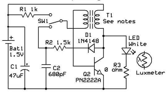
So, there are only three real things to change - the transformer, the transistor, and the LED. Some LEDs are fairly dim by design, even when properly supplied. Assuming this isn't the problem, that leaves the transistor and the toroid.

Without doing the math, I'd say its safe to say you want a transistor with a fairly high beta value (the ratio of Collector current to base current) that can handle quite a bit of current.

The websites posted in the comments are pretty accurate. You need as few coils as possible around a reasonably sized toroid to store the most energy possible in a very short time. Don't forget that 1 volt across a very low resistance wire can still make for a significant amount of current, so don't use itty bitty magnet wire. The other feedback coil (left hand) can be relatively wimpy, in comparison - transistor base current through that resistor should be on the order of microamps.

LEDs would get dim in these circuits in the primary winding had way too much inductance, the transistor was relatively high in on-state resistance, or, quite possibly, from not having the coils wound in opposition to each other - the LED might find just enough juice from the battery to bias weakly, and the feedback path would simply hold the transistor in a hard-off reverse biased state.

0

I know this is an old question, but recently I experimented with this circuit a bit and I found a couple of things that added a bit more to the design.

Especially if you're working off of something with ultra low power like a small solar panel. I'm going to draw my toroid a bit different than @SeanBoddy but it's the same thing. I found a smaller sized (T35 Ferrite Core, 16mmx9.6mmx6.3mm, 3.87uH part : 495-76691-ND, Wound parallel, 12x with, well I used two straightened out cat 6e wires cut out of the bigger cable - about 30cm long)

*Note, because Circuit Lab doesn't have this toroid in its collection, this schematic won't run:

schematic

simulate this circuit – Schematic created using CircuitLab

Here's what I found. Using an additional inductor at the collector (experiment with different sizes is a MUST) gives different voltages and power outputs. It can give slight variations to your duty cycle and definitely to your frequency.

The additional resistor at the emitter will add DC bias to your signal which may be nice if you are trying to drive a mosfet at your next stage. Either way, your voltage output will be higher. This resistor will absolutely increase your duty cycle at the cost of your Vpp amplitude. Find a good balance.

You'll always get better current if your inductor doesn't fully discharge, so if you place a capacitor here that can charge and discharge fast enough (depending on the power output of your battery source) it will work better. If this is an ultra low power source, a very small capacitor might be the best thing.

These are the things I've experimented with. With the same battery I have results ranging from 5V to 22V Vpp and under load at the Output Capacitor 1mA to 32mA just by changing these three things.

RobMcN
  • 165
  • 9