3

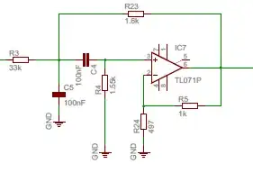
I am working on a synth module that converts a square wave (generated digitally: High - 10v; Low - 0v; Duty cycle = 50%) to triangle wave output. I've found this schematic that works for an already extended range of frequencies - 470Hz to 20kHz: enter image description here It also successfully works in Ltspice: enter image description here Output for 5kHz: enter image description here Output for 500Hz: enter image description here
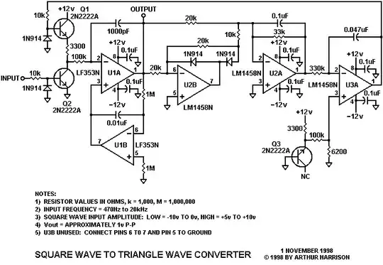
However, in the musical sense I would like to go down to lower frequencies such as 50Hz. Current schematic struggles with such low frequencies: enter image description here

Adjusting capacitors (LTspice schematic C1=100n; C2=100n;C8=470n) seems to be a solution for 50Hz signal: enter image description here
I think it's possible to change these values during operation. Placing analog switches (e.g. CD4066) is probably something I should try: enter image description here
The issue with this approach might be a sharp volume change in case switches are connected/disconnected by some voltage signal related to specific input frequency.

Could anyone provide any advice:

  1. Would this approach of using switches work?
  2. Is there any better solution for continuous adjustment of operation for this circuit?
  • 1
    Study CD4046 VCO. Like many function generators, the actual oscillator starts with triangle, and generates square from that. The 555 chip takes a somewhat similar approach. – glen_geek Nov 13 '22 at 15:53
  • @glen_geek thank you for the idea - I will take a look at the datasheet. However I was hoping of being able to input external square signal and processing it to form triangle – Ivan Demyachenko Nov 13 '22 at 16:27
  • See also my answer at this post. I forgot the "Howland" pump ... which can also be used. https://electronics.stackexchange.com/questions/645611/how-does-this-constant-current-circuit-work/645652 – Antonio51 Dec 11 '22 at 08:51

2 Answers2

5

I can't find any results for 554UD1. I assume it's an op-amp.

Do this:

  1. Do not use OP-amps as comparators. Doing so is like using a knife to turn a screw instead of a screwdriver. Use instead a comparator with a rail-to-rail output.
  2. Do not use a BJT for Q4, because its on voltage is too high and varies. Use instead a MOSFET.
  3. Do not convert a square wave to triangle with an integrator, because its output level is inversely proportional to frequency; amplifying that output at high frequencies adds noise. Instead, do it the other way around: convert a triangle wave to a square wave. Use a standard triangle wave generator circuit (it uses an op-amp and an integrator plus a comparator as a Schmitt trigger to convert it to a square wave, which is then fed back to the input of the integrator). Then, add a PLL (Phase Lock Loop) to lock this square wave to the incoming square wave. (Granted, locking over such a wide range of frequencies will be tricky.) Note: when the input frequency jumps, in your present solution the volume wavers, while in my proposed solution the frequency glides.
  4. For a variable resistor to set the frequency ("R" in the circuit I linked), use an Optical FET: H11F1
  5. In your schematic, show where the output is.
Davide Andrea
  • 16,164
  • 4
  • 33
  • 62
3

Perhaps another approach with current mirrors.

This circuit transforms the rectangular input into a triangle at the same frequency.
There are some limits and some sort of "feedback" must be used.

The parameter here is nn, can range from 0.1 to 100 with the devices used.
Which mean tested from 2 Hz to 2000 Hz.

enter image description here

NB: one can add two resistors (5 to 10 Meg not necessarily equal, one wired from VT to ground, and the other wired from VT to +12V) for offsetting voltage at Vt.
I tried 5 Meg for the "up" resistor and 10 Meg for the "low". Slight change of DC voltage ("up").

Tried with an integrator ... see the defect at 10 kHz.
NB: the multiplier should be a "multiplying" DAC.

enter image description here

Here is the practical "currents" generator. 1 Ohm should not used.

enter image description here

Modified with Wilson mirrors. More closest values of current.
Be aware for "power dissipation" for the BJT ... (for some BJT, 20 mA with 15 V ... ~ 360 mW ...)

enter image description here

DC Analysis

enter image description here

Antonio51
  • 11,004
  • 1
  • 7
  • 20
  • It looks like this circuit is putting current into a capacitor to integrate the square wave into a triangle. In that case the output amplitude will be dependent on frequency, which the OP wanted to avoid. – user4574 Nov 13 '22 at 20:59
  • This is only the basic idea. I added the fact that some "sort of feedback" must be used. The parameter nn is for the simulation. A circuit for this function must be done (measure the input period and this will adapt the current reference for it, thus the amplitude). In the simulation, it is very well working, and quasi with no delay in the range I tested. – Antonio51 Nov 13 '22 at 21:08
  • Could you please clarify what's the purpose of R5 and R8 in your schematic? Are they floating or connected to something? I will try testing this idea tomorrow in LTspice – Ivan Demyachenko Nov 13 '22 at 22:41
  • R5 and R8 are just used for checking the complementary mirror currents in transistor Q3-Q4 and Q5-Q6. – Antonio51 Nov 14 '22 at 06:16
  • I did not used yet this idea with an integrator, and it can also works. Idea is to replace the input resistor with a DAC "feeding" a variable current "locked" on the period value which is "known" with a sample/hold. Then calculating frequency (proportional to current) by inverting period (1/x). This can be made digitally and fed to DAC. – Antonio51 Nov 14 '22 at 06:26
  • I've simulated your circuit in LTspice - it works as you described. However could you please clarify how current feeding supposed to look like. I was hoping to convert frequency to voltage with something similar to [this](https://cxem.net/beginner/images/beginner164-3.jpg) (capacitor C3 and resistor R4 adjusted to appropriate values). Instead of inverting @OP1.2 - configure op amp to shift value into positive DC region. Therefore low freq would correspond to high V and high freq to ~0V. – Ivan Demyachenko Nov 14 '22 at 12:09
  • Then feed this voltage to voltage to current converter such as [this](https://northcoastsynthesis.com/news/exponential-converters-and-how-they-work/555-expo.png). Current is then applied to integrator. Does this idea make sense or it should be done in a different way? – Ivan Demyachenko Nov 14 '22 at 12:12
  • Hum ... Must check ... – Antonio51 Nov 14 '22 at 12:44
  • Here is how I think it should look like: [schematic](https://ibb.co/4VntLCd) . Though I am pretty certain that's not how I am supposed to connect current source to these mirrors. – Ivan Demyachenko Nov 14 '22 at 15:56
  • Not that wiring. Q3 and Q8 are supposed to receive the same "floating" variable current ... Not yet thought about how to do it. Probably a BJT with an op-amp controlling the floating flow of current. – Antonio51 Nov 14 '22 at 17:08
  • Keep on. I am checking an idea. I think it will work. – Antonio51 Nov 14 '22 at 18:33
  • Ok. practical circuit in answer. Not checked in "generator", but should be working. – Antonio51 Nov 14 '22 at 19:42
  • Thank you very much for such an extensive answer! I will try simulating this approach and post my results. – Ivan Demyachenko Nov 14 '22 at 20:44
  • Here is the [current version](https://ibb.co/Y0WfPMJ). I will experiment with different resistors/capacitors values to improve [settling time](https://ibb.co/8XRxLLq). However a shape of output [waveforrm](https://ibb.co/ZxpR85J) seems to be unsymmetrical. Could you please help me to understand why is it "flat" at the bottom and centered around 1.4V? – Ivan Demyachenko Nov 15 '22 at 08:17
  • Adjusting C8 to 100n improves triangle output for desired frequency range. Though it is still flat at the bottom – Ivan Demyachenko Nov 15 '22 at 08:53
  • 1
    The "discharge" current is a little too big, so it discharges completely the capacitor. Mirror current with discrete devices are not very "good". A structure as a Wilson could help https://wiki.analog.com/university/courses/electronics/text/chapter-11 and also an current offset, not checked. Try also a little resistor at the emitter of Q4. – Antonio51 Nov 15 '22 at 09:04
  • AC-coupling the input signal seems to make output output symmetrical. Do you think it would be possible to balance current difference by an op-amp that monitors average output level like [this](https://ibb.co/tcCpD6b)? Does connecting it to Q9 and Q10 via diodes make sense? Simulation seems to work. – Ivan Demyachenko Nov 15 '22 at 12:57
  • Not checked coupling AC. Monitoring average output is a good idea. If the simulation seems to work, then ... all is ok? – Antonio51 Nov 15 '22 at 13:16