For a book that professes to be "The Hidden Language of Computer Hardware and Software" they sure seem to miss the mark here. (book ref here)
tl, dr version: there is no current flow. The text shown is a behavioral logic model, using switches and lamps as metaphors for logic inputs and outputs of ‘1’ and ‘0’ or ‘high’ and ‘low’. They aren’t representing actual physical devices. In this diagram they only represent logical values and behaviors.
I came to to this conclusion after having a peek at some of the interactive sims the author uses. They rely heavily on these switch-and-lamp metaphors, until they don’t.
Earlier in the book they show relay logic, and as such hints at physical behaviors: switch closes, coil energizes, contacts close, current flows to the lamp.
They then transition to logic gates, which are behavioral symbols representing Boolean equations (but nonetheless can also have physical representations, as we’ll see below.)
Even later in the book, the author dispenses with the switches-and-lamps metaphors, going full behavioral logic using 1’s and 0’s.
Back to this troublesome diagram. Being behavioral symbols, the ‘switches’ and ‘lamp’ don’t draw or supply current any more than a math equation does. They’re representing logic values, using a connection to ‘V’ as a logic ‘1’ and non-connection as ‘0’.
For this diagram then, we’re in Boolean town. Replace those metaphors in your mind with logic ‘1’ / logic ‘0’ and forget about current or electrons.
Fortunately we’re not constrained by the author’s metaphors. We can move between the logical and physical using an online, interactive tool: Falstad.
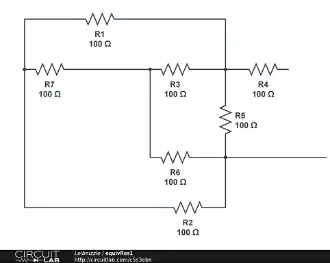
With Falstad (and other sims, including CircutLab here on this website) we can make a working NOR latch as a symbolic logical model with gates, and as physical one with real devices showing how current flows (simulate it here):
What’s going on?
The left-hand sim shows the NOR latch logic gate diagram - the behavioral model. The power connections are not shown, but implied to be 5V. (In the sim, you can edit each gate to change this voltage.) Set the latch by manipulating the upper switch, see that current flows from the ‘hidden’ power connection in the NOR symbol to the bulb, just like in the textbook diagram. (A lot of current flows into that bulb - its resistance is quite low until the bulb warms up: Falstad is modeling a lamp’s physical behavior.)
The right hand sim shows two CMOS NOR gates each constructed from FET switches - the physical model. Here, the power and ground connections are explicit. Manipulate the upper switch to set the latch, and observe the current flows from 5V, through the lower gate's p-FET, then to the lamp. (The series resistor is a hack to make the sim converge because of the bulb’s low starting resistance.) It, too, operates the same as the text.
Logical or physical, they both work. Most of the time, logical is more convenient to think about and more efficient to simulate. For these reasons, the bulk of digital design work is done in the behavioral logic realm.
But in the real world, physical behavior matters too. Many of the questions here on EE Stackexchange are in fact about how physical digital hardware actually works. Stuff like voltage levels, current paths, switching speed, and so forth.
You will see both languages spoken here: the purity of Boolean logic, and the complexity and analog-ness of devices that implement it. As designers and users of logic devices it pays to be fluent in both.
Now that you have a bit of insider knowledge, I have another issue with this text. They show simple single-pole switches connecting gates to a voltage, which we now understand to be a metaphor for a digital 1 or 0. Beware: this isn't realistic. Gate inputs need to be driven explicitly high or low, especially CMOS, for gates to work properly.
In fact, if you tried to breadboard the textbook circuit as-is using SPST switches with CMOS or TTL gates, it will fail. That's why my sim uses SPDT (single-pole, double-throw) switches that connect to 5V or GND to the inputs.
Why? Here's how different logic families behave with an unconnected input:
- CMOS: unpredictable, may pick up noise and oscillate
- TTL: defaults to a logic '1'
- RTL, DTL (old logic families, obsolete): defaults to a logic '0' (so this would work)
Falstad has simulations of these different gate technology types (CMOS, RTL, DTL, TTL) that you can try. This will help you get a sense of how real-world gates behave.
Another detail: Falstad's logical gate sim defaults unconnected inputs to '0'. So in the left-hand sim, the switches could be SPST, just like the text. I didn’t do that because I’m trying to show good practice.
Speaking of good practice, if you were to code this NOR latch in a hardware description language like Verilog or VHDL, the compiler would give you a warning about an unconnected input, and your sim would show the output as unknown, or ‘X’.
Just remember, don't get caught out by that rookie mistake. Connect gate inputs to a valid logic level, even the unused ones. Even in Verilog.
Oh, and there’s another problem in physical-land too: incandescent lamps need a lot of current until they’re warmed up. That’s why I had to add a series resistor to the physical sim. Were you to use a lamp in a breadboard lash-up, it would likely fail because the lamp would not allow that lower gate to be driven high to set the latch. This would be especially true for TTL which has weak high-drive; RTL and DTL wouldn’t work at all.
This problem could be fixed by adding a buffer to drive the lamp, or by using an LED with a series resistor.
Identifying and solving problems like these is where fluency in both logical and physical really helps.
The takeaway: the book is introductory, confuses logical and physical, and if taken literally could get you into trouble. Good on you for noticing that and raising the question.
One more thing: yes, electron flow is negative to positive, which, confusingly, is opposite of what is called conventional current flow, which is positive to negative. It’s historical, because our understanding of electron theory came many decades after basic electricity. Blame Ben Franklin.
But know that when you’re talking about electricity, it’s overwhelmingly the ‘conventional’ current flows positive-to-negative notation that’s used. But if you prefer, Falstad lets you choose electron flow instead of ‘conventional’.

