4

Recently we installed some speakers into our church's ceiling. I've worked a little bit with analog circuits before, so I thought about putting a volume potentiometer before the amplifier.

I don't know if this circuit will cause any issues with the amplifier itself. Does this look right? The signal is from a soundboard RCA out, so it's low level. There was not a jack available, but the end will just be L, R, and GND. All GNDs are tied together.

schematic

simulate this circuit – Schematic created using CircuitLab

ocrdu
  • 8,705
  • 21
  • 30
  • 42
ACEHOBOJOE
  • 45
  • 4
  • 1
    that's pretty much how a volume control works. Should work as long as the amp has a high input impedance (which it probably does) – user253751 Nov 10 '22 at 03:05
  • 1
    It might be worth checking for potentiometers that are not linear but exponential. Because sound at halve the amplitude is not percieved as half as loud... – kruemi Nov 10 '22 at 09:52
  • 1
    You can find potentiometers of the kind that @kruemi described if you search for "audio taper potentiometer." – Solomon Slow Nov 10 '22 at 14:44

1 Answers1

2

This circuit should cater for all eventualities.

Pots

I am not familiar with the output of that particular soundboard but including capacitors C1 & C3 will mitigate the possibility of any DC offset at the output of the soundboard. The circuit will still work without C1 & C3, even if there is a dc offset at the output of the soundboard, but you shouldn't pass dc current through a pot because it can result in the pot sounding "scratchy".

Capacitors C2 & C4 are included to cater for the possibility of any dc offset at the input of the amp. If the amplifier is single voltage supply then its input will be biased to mid-rail. In this case you must add capacitors C2 & C4.

Even if there is no large dc offset at either the output of the soundboard or at the input to the amp (say the amp is dual voltage supply) and both the input to the pot and the output from it are nominally biased to ground (0 V), I would still recommend including all four capacitors. C2 & C4 will then remove any dc offset across the pots which could be caused by the amps' input bias currents.

I have specified bipolar capacitors, otherwise known as non-polarised. Which will enable a voltage of either polarity to be applied to them (within their voltage range specification) without risk of damage to them. So, using bipolar capacitors could be necessary if both the output from the soundboard and the input to the amp are biased to 0 V. Through-hole bipolar capacitors are larger and more expensive than their equivalent uni-polar cousins.

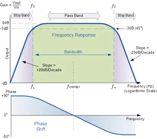
The pots in conjunction with C2 & C4 form high pass filters and you will find that, at low and high volume pot settings when the output resistance of the pots is relatively low, there will be some loss of low-end frequencies (bass). If this is a problem for you then increase the values of capacitors C2 & C4.

I expect you've already found out that dual-gang (stereo) pots are obtainable.

You will find that, if there is a large dc mismatch between the soundboard's output and the amp's input, the capacitors will cause a sound "thump" through the speakers at power-up and power-down. This is difficult to avoid when there are capacitors in the audio signal path without adding some extra more complex circuitry which disconnects the speakers from the amps for a few seconds when power is applied or removed.

  • I disagree with the statement that non-polarized capacitors are larger and more expensive. You can get 22 μF X5R ceramics in 0402 (0603 is easier to find, though); I don't think they even *make* tantalums or aluminum caps that small. – Hearth Nov 10 '22 at 05:27
  • @Hearth Statement modified. –  Nov 10 '22 at 05:34
  • [Still substantially smaller than your average electrolytic.](https://www.digikey.com/en/products/detail/tdk-corporation/FG24X5R1E226MRT06/5802981) Slightly more expensive, but we're talking a matter of cents here. Unless you're mass producing it, the price difference won't matter. – Hearth Nov 10 '22 at 05:46
  • Another thing is, even if possible, do you really want to pass audio through a X5R or tantalum at all, due to their nonlinearities. At least it is not very common. – Justme Nov 10 '22 at 05:49
  • @Hearth Oh I see what your problem is. Your thinking is limited to ceramic capacitors, not a good idea - see Justme's comment. I would use electrolytics in this situation. –  Nov 10 '22 at 06:21
  • I will use electrolytics for this. That was a great answer. A couple of notes: 1. The amplifier will always be on, but the soundboard will not. This is something that I can't really add a switch for at the moment. 2. I'm surprised that both the amplifier and soundboard don't have caps on their respective inputs and outputs. But this makes sense. 3. Now I'll have to logistically figure out a good way to put some caps behind this wall plate. Right now the dual pot is just attached to the drilled hole. – ACEHOBOJOE Nov 10 '22 at 14:12
  • @Justme I don't do a lot of work with audio; my specialty is switching power supplies. I would have thought the audio signal wouldn't be large enough amplitude to be significantly distorted, as long as you get at least a 10~20 volt rated capacitor. Tantalum electrolytics aren't really any more nonlinear than aluminum electrolytics, as far as I know. Though if you really want linearity, my understanding is that polypropylene film is the way to go. – Hearth Nov 11 '22 at 05:18