9

I have been trying this exercise for a while and I can't solve it. enter image description here
What they ask me to find is $$\frac{V_2\left(s\right)}{V_s\left(s\right)}=?$$

My best attempt has been the following enter image description here
\begin{array}{l}\left[1\right]\ V_s\left(s\right)=R_sI1_{\left(s\right)}+Z\left(I1_{\left(s\right)}-I2_{\left(s\right)}\right)\\ \left[2\right]\ g_m=I2_{\left(s\right)}-I3_{\left(s\right)}\\ \left[3\right]\ \frac{I2_{\left(s\right)}}{sC_{\mu }}+R_LI3_{\left(s\right)}+Z\left(I2_{\left(s\right)}-I1_{\left(s\right)}\right)=0\\ \frac{I2_{\left(s\right)}}{sC_{\mu }}+R_LI3_{\left(s\right)}=Z\left(I1_{\left(s\right)}-I2_{\left(s\right)}\right)\\ \left[2\right]\ g_m+I3_{\left(s\right)}=I2_{\left(s\right)}\\ Rem\\ \left[1\right]\ V_s\left(s\right)=R_sI1_{\left(s\right)}+\frac{g_m+I3_{\left(s\right)}}{sC_{\mu }}+R_LI3_{\left(s\right)}\\ \frac{\ V_s\left(s\right)}{I3_{\left(s\right)}}=\frac{R_sI1_{\left(s\right)}}{I3_{\left(s\right)}}+\frac{g_m}{sC_{\mu }I3_{\left(s\right)}}+\frac{1}{sC_{\mu }}+R_L\\ \left[\frac{\ V_s\left(s\right)}{I3_{\left(s\right)}}=\frac{sC_{\mu }R_sI1_{\left(s\right)}+g_m+I3_{\left(s\right)}\left(1+sC_{\mu }R_L\right)}{sC_{\mu }I3_{\left(s\right)}}\right]\\ \left[2\right]\ I2_{\left(s\right)}-g_m=I3_{\left(s\right)}\\ \frac{\ V_s\left(s\right)}{I3_{\left(s\right)}}=\frac{sC_{\mu }R_sI1_{\left(s\right)}+g_m+\left(I2_{\left(s\right)}-g_m\right)\left(1+sC_{\mu }R_L\right)}{sC_{\mu }\left(I2_{\left(s\right)}-g_m\right)}\\ \left[3\right]\ \frac{I2_{\left(s\right)}}{sC_{\mu }}+R_LI3_{\left(s\right)}=ZI1_{\left(s\right)}-ZI2_{\left(s\right)}\\ \frac{I2_{\left(s\right)}}{ZsC_{\mu }}+\frac{R_LI3_{\left(s\right)}}{Z}+I2_{\left(s\right)}=I1_{\left(s\right)}\end{array}

After getting there I don't know what to do

[Update]

I was able to solve it now, thanks to everyone who replied and showed me so many methods.

What I did was transform the voltage source, then apply a divider and get the equation through nodes.

enter image description here

So I got the following equations

$$\begin{array}{l}\sum _{ }^{ }i_e\left(t\right)=\sum _{ }^{ }i_s\left(t\right)\\ \left[1\right]\ \frac{V_s\left(s\right)}{R_s}=g_tV_t\left(s\right)+sC_{\eta }V_t\left(s\right)+sC_{\mu }\left(V_t\left(s\right)-V_2\left(s\right)\right)\\ \left[2\right]\ sC_{\mu }\left(V_t\left(s\right)-V_2\left(s\right)\right)=g_m\cdot V_t\left(s\right)+\frac{V_2\left(s\right)}{R_L}\\ \ sC_{\mu }V_t\left(s\right)-sC_{\mu }V_2\left(s\right)-g_m\cdot V_t\left(s\right)=\frac{V_2\left(s\right)}{R_L}\\ \ V_t\left(s\right)\left(sC_{\mu }-g_m\right)=\left(\frac{1}{R_L}+sC_{\mu }\right)V_2\left(s\right)\\ V_t\left(s\right)\left(sC_{\mu }-g_m\right)=\left(\frac{1+R_LsC_{\mu }}{R_L}\right)V_2\left(s\right)\\ V_t\left(s\right)=V_2\left(s\right)\left(\frac{1+R_LsC_{\mu }}{R_L\left(sC_{\mu }-g_m\right)}\right)\\ Sus\ 1\\ \frac{V_s\left(s\right)}{R_s}=g_tV_t\left(s\right)+sC_{\eta }V_t\left(s\right)+sC_{\mu }\left(V_t\left(s\right)-V_2\left(s\right)\right)\\ \frac{V_s\left(s\right)}{R_s}=g_tV_2\left(s\right)\left(\frac{1+R_LsC_{\mu }}{R_L\left(sC_{\mu }-g_m\right)}\right)+sC_{\eta }V_2\left(s\right)\left(\frac{1+R_LsC_{\mu }}{R_L\left(sC_{\mu }-g_m\right)}\right)+sC_{\mu }\left(V_t\left(s\right)-V_2\left(s\right)\right)\\ \frac{V_s\left(s\right)}{R_s}=g_tV_2\left(s\right)\left(\frac{1+R_LsC_{\mu }}{R_L\left(sC_{\mu }-g_m\right)}\right)+sC_{\eta }V_2\left(s\right)\left(\frac{1+R_LsC_{\mu }}{R_L\left(sC_{\mu }-g_m\right)}\right)+g_m\cdot V_2\left(s\right)\left(\frac{1+R_LsC_{\mu }}{R_L\left(sC_{\mu }-g_m\right)}\right)+\frac{V_2\left(s\right)}{R_L}\\ \frac{V_s\left(s\right)}{R_sV_2\left(s\right)}=g_t\left(\frac{1+R_LsC_{\mu }}{R_L\left(sC_{\mu }-g_m\right)}\right)+sC_{\eta }\left(\frac{1+R_LsC_{\mu }}{R_L\left(sC_{\mu }-g_m\right)}\right)+g_m\left(\frac{1+R_LsC_{\mu }}{R_L\left(sC_{\mu }-g_m\right)}\right)+\frac{1}{R_L}\\ \frac{V_s\left(s\right)}{R_sV_2\left(s\right)}=\frac{g_t+g_tR_LsC_{\mu }}{R_L\left(sC_{\mu }-g_m\right)}+\frac{sC_{\eta }+s^2C_{\eta }C_{\mu }R_L}{R_L\left(sC_{\mu }-g_m\right)}+\frac{g_m+g_msC_{\mu }R_L}{R_L\left(sC_{\mu }-g_m\right)}+\frac{sC_{\mu }-g_m}{R_L\left(sC_{\mu }-g_m\right)}\\ \frac{V_s\left(s\right)}{R_sV_2\left(s\right)}=\frac{g_t+g_tR_LsC_{\mu }+sC_{\eta }+s^2C_{\eta }C_{\mu }R_L+g_m+g_msC_{\mu }R_L+sC_{\mu }-g_m}{R_L\left(sC_{\mu }-g_m\right)}\\ \frac{V_s\left(s\right)}{R_sV_2\left(s\right)}=\frac{s^2C_{\eta }C_{\mu }R_L+s\left(C_{\eta }+C_{\mu }+g_tR_LC_{\mu }+g_mC_{\mu }R_L\right)+g_t}{R_L\left(sC_{\mu }-g_m\right)}\\ \frac{R_sV_2\left(s\right)}{V_s\left(s\right)}=\frac{R_L\left(sC_{\mu }-g_m\right)}{s^2C_{\eta }C_{\mu }R_L+s\left(C_{\eta }+C_{\mu }+g_tR_LC_{\mu }+g_mC_{\mu }R_L\right)+g_t}\\ \left[\frac{V_2\left(s\right)}{V_s\left(s\right)}=\frac{sC_{\mu }-g_m}{s^2C_{\eta }C_{\mu }R_L+s\left(C_{\eta }+C_{\mu }+g_tR_LC_{\mu }+g_mC_{\mu }R_L\right)+g_t}\cdot \frac{R_L}{R_s}\right]\\ where\ g_t\ =\frac{1}{R_s}+\frac{1}{r_n}\end{array}$$

Thank you all for responding
  • 2
    The first simplification I'd do is combine Vs, Rs and Rn into a new lower value voltage source with a single series resistor of Rs || Rn. – Andy aka Nov 06 '22 at 16:22
  • What question are you supposed to answer about these circuits? – The Photon Nov 06 '22 at 16:55
  • @ThePhoton My mistake, I forgot to put what they asked for is V2(s)/Vs(s) – ALEXANDER MONTOYA REYES Nov 06 '22 at 17:02
  • @Andyaka That is something new for me, could you tell me the name of the method it would be to do that? – ALEXANDER MONTOYA REYES Nov 06 '22 at 17:03
  • It's called Thevenin source conversion: https://www.cpp.edu/~elab/projects/project_08/index.html#:~:text=Norton's%20Theorem-,Th%C3%A9venin's%20Theorem,voltage%20source%20and%20one%20resistor.&text=Th%C3%A9venin%20equivalent%20circuit%20represents%20a,with%20a%20since%20resistance%20Rth. – Andy aka Nov 06 '22 at 17:08
  • @Andyaka What happens with the capacitors when applying thevenin and Norton? can I convert them into Z1..Z2 and apply Z1Z2/Z1+Z2 without any problem? – ALEXANDER MONTOYA REYES Nov 06 '22 at 17:14
  • No you can't because you need to keep Cn in place to develop the voltage across it that controls the current source. Is this circuit for a FET? – Andy aka Nov 06 '22 at 17:17
  • 1
    Your second equation looks wrong -- $$g_m$$ should be $$g_m V(s)$$ – Scott Seidman Nov 06 '22 at 17:23
  • 2
    it seems you can use nodal analysis to solve it.You may have missed a equation. You can transform voltage source \$V_s\$ to current source on left. Combine resistors \$R_s\$ and \$r_n\$. . Looks doable to me. You can get the nodal voltage for \$V_2\$ with nodal analysis. Use that to calculate \$\frac{V_2}{V_s} \$ – Amit M Nov 06 '22 at 17:29
  • @Andyaka emmm I don't think it's for a Fet, it's just a transfer function exercise – ALEXANDER MONTOYA REYES Nov 06 '22 at 18:08
  • @AmitM You mean this? then use nodes and get the answer? I can't combine that with Cn because it already has proposed addresses? is that, those v(t) also confuse me https://postimg.cc/gallery/NM9mm8z – ALEXANDER MONTOYA REYES Nov 06 '22 at 18:10
  • ALEXANDER MONTOYA REYES, the conductance \$g_t\$ in image one seems wrong . The equivalent resistance of Rs and rn as \$\frac{R_s r_n}{R_s+r_n} \$ . So the conductance would be inverse of that. The current source on left in place of voltage source would be Vs/Rs. Impedance of capacitancitors as 1/sc is correct. You have everything to write nodal equations and solve for \$V_2\$ – Amit M Nov 07 '22 at 07:01
  • You can either use conductance or impedance sto solve for V2. Dont mix both. There are two methods. Just write three linear equation and solve V2. Use kramers rule if you like. The other is to construct matrices with conductances in the form [g][V] = [I] .Doing calculations with matrices may be a bit hard if you dont have a scientific calculator. – Amit M Nov 07 '22 at 07:13
  • This looks suspiciously similar to the equivalent circuit of a BJT amplifier at high frequencies.Where did you get that exercise from? – Miss Mulan Nov 08 '22 at 20:24
  • @MissMulan In the description of this exercise it says "Application exercises: 1) For the small-signal equivalent circuit of the transistor amplifier shown, obtain the transfer function H(s) = V2(s)/Vs(s). " I'm surprised how without this detail some managed to deduce that this was related to an amplifier – ALEXANDER MONTOYA REYES Nov 08 '22 at 20:44
  • @MissMulan I got the exercise from here, it is a document in Spanish, page 20 of the pdf https://www.fceia.unr.edu.ar/tci/utiles/Apuntes/CAP%2012-2013%20LAPLACE.pdf – ALEXANDER MONTOYA REYES Nov 08 '22 at 20:45
  • @ALEXANDERMONTOYAREYES I just did it in college like honestly yesterday. – Miss Mulan Nov 08 '22 at 20:46
  • @MissMulan I also managed to solve it like 57 minutes ago, god that was difficult – ALEXANDER MONTOYA REYES Nov 08 '22 at 20:57

6 Answers6

6

I don't know where you got that exercise but it is not an easy one. I have used the fast analytical circuits techniques (FACTs) described in my book on the subject. You first start by determining the dc gain and the time constants of the circuit:

enter image description here

You do the same for the zeroes realizing that only the series capacitor provides one. Assemble all the time constants together as in the below picture:

enter image description here

To check this expression, I have simulated the circuit in SIMetrix and imported the data in Mathcad. As you can see below, a perfect match:

enter image description here

Verbal Kint
  • 20,420
  • 1
  • 16
  • 50
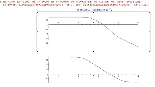
  • Just a remark ... I think that this circuit is an ac "equivalent" BJT (pi circuit or "Giaccoletto" schematic ?) circuit. So some value I have chosen are the "parameters" of one BJT. It is probably the fact of my different curves I have. ( Rs:=100: Rn:=1000: RL := 1000: gm := 0.040: Cn:=100*1e-12: Cu:=1e-12). What is ok is that I found 1 zero and two poles. – Antonio51 Nov 06 '22 at 19:02
  • @Antonio51, you are right, with the base-emitter capacitance and the collector-base capacitor. Yes, there is always a RHP zero with the collector-base capacitor and this is a second-order circuit. – Verbal Kint Nov 06 '22 at 19:38
  • These techniques are too advanced, I'm not even going to see them in my course, holy shit I didn't even know there was a way to check this type of problem. Can you tell me what those bars mean || ? I took the exercise from here: https://www.fceia.unr.edu.ar/tci/utiles/Apuntes/CAP%2012-2013%20LAPLACE.pdf page 20 of the pdf thanks for replying, that was crazy – ALEXANDER MONTOYA REYES Nov 06 '22 at 19:42
  • @ALEXANDERMONTOYAREYES Note that this exercise can be solved (I think so, EE&O) by "paralleling" two matrices... One matrix is only ... composed by Cu. – Antonio51 Nov 06 '22 at 19:50
  • @ALEXANDERMONTOYAREYES, yes, these techniques are quite efficient but not difficult to learn. One big advantage is the ability to solve one intermediate step to fix a guilty coefficient as I had in the first posting for the zero. After correction, the zero is fixed and the rest hasn't been touched. I encourage to further dig the subject and my [APEC 2016](https://cbasso.pagesperso-orange.fr/Downloads/PPTs/Chris%20Basso%20APEC%20seminar%202016.pdf) is a good start. – Verbal Kint Nov 06 '22 at 22:15
4

As pointed out by @Verbal Kint, it is not an easy circuit (because of the two capacitors).

Here is a Maple sheet for this, the values chosen are of a "common" BJT EC configuration.

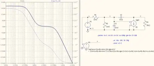
As "usual", I did the same thing with a simulator (did not check all yet).
Made with microcap v12.

enter image description here

enter image description here

enter image description here

Antonio51
  • 11,004
  • 1
  • 7
  • 20
  • How did you get that answer? through a program? I took that exercise from here https://www.fceia.unr.edu.ar/tci/utiles/Apuntes/CAP%2012-2013%20LAPLACE.pdf and it is exactly the same result, this cannot be done with conventional methods? at least what I had done in my attempt was right or from the beginning I was wrong – ALEXANDER MONTOYA REYES Nov 06 '22 at 19:50
  • @ALEXANDERMONTOYAREYES Answer calculated by Maple. Just need insert the "right" equations ... Note that this exercise can be solved (I think so, EE&O) by "paralleling" two matrices... One matrix is only ... composed by Cu. If Cu is "wiped" ... problem is simpler and "obvious". – Antonio51 Nov 06 '22 at 19:52
  • I don't quite understand how you got the equations, you combined rn with Cu, right? and then how do you deduce the equations to solve it, could you explain that detail to me? – ALEXANDER MONTOYA REYES Nov 06 '22 at 20:17
  • rn (R2) combined with cn (C2). 2 KCL and 2 KVL equations, see my schematic. Just let v2 (voltage output vo). zp is R2//C2, voltage accross zp is = zp*izp. NB: I did not take care of Ru (R3), which is paralleled with Cu (C1). – Antonio51 Nov 06 '22 at 21:12
3

If you have access to and can use a symbolic solver (or even a numerical one) then you can use the voltages, since it's ony two nodes. For example, in the picture below, using the annotated node labes, you can use Python to solve it:

import sympy as sp
sp.var('s')
sp.var('v1 v2 vs')
sp.var('Rs rn Cu Cn gm RL')
eq1=sp.Eq(v1*(1/Rs+1/rn+s*Cn+s*Cu), vs/Rs+v2*s*Cu)
eq2=sp.Eq(v2*(s*Cu+1/RL)+v1*gm, v1*s*Cu)
sp.solve([eq1, eq2],[v1, v2])

{v1: (Cu*RL*rn*s*vs + rn*vs)/(Cn*Cu*RL*Rs*rn*s**2 + Cn*Rs*rn*s + Cu*RL*Rs*gm*rn*s + Cu*RL*Rs*s + Cu*RL*rn*s + Cu*Rs*rn*s + Rs + rn), v2: (Cu*RL*rn*s*vs - RL*gm*rn*vs)/(Cn*Cu*RL*Rs*rn*s**2 + Cn*Rs*rn*s + Cu*RL*Rs*gm*rn*s + Cu*RL*Rs*s + Cu*RL*rn*s + Cu*Rs*rn*s + Rs + rn)}

(I see there are two answers now, I'll finish this since it involves Kirchhoff, which is what you tried, but the other way)

The test is easy enough:

test confirmed

I've shifted V(x) a bit otherwise they would completely overlap, just like the phase plots (i.e. the Laplace expression and the circuit are identical).


[edit]

If you have problems deciphering the code, here are the MathJax equations:

$$\begin{cases} V_1\left(\dfrac{1}{R_S}+\dfrac{1}{r_n}+sC_{\eta}+sC_{\mu}\right)&=\dfrac{V_S}{R_S}+V_2sC_{\mu} \\ V_2\left(sC_{\mu}+\dfrac{1}{R_L}\right)+g_mV_1&=V_1sC_{\mu} \end{cases} \tag{1}$$

There are two solutions, out of which the second one is of interest:

$$ \dfrac{V_2}{V_S}=-\dfrac{r_nR_LC_{\mu}s-g_mr_nR_L}{r_nR_LR_SC_{\eta}C_{\mu}s^2+\Biggr(\biggr(R_S\big(C_{\mu}(g_mR_L+1)+C_{\eta}\big)+R_LC{\mu}\biggr)r_n+R_LR_SC_{\mu}\Biggr)s+r_n+R_S} \tag{2} $$


[edit 2]

For the sake of completeness, here's the system of equations that can take you to solve the problem using your approach:

$$\begin{cases} 1&=R_Si_1+(i_1-i_2)r_n \\ (i_1-i_2)r_n&=\dfrac{i_2-i_3}{sC_{\eta}} \\ \dfrac{i_2-i_3}{sC_{\eta}}&=\dfrac{i_3}{sC_{\mu}}+g_m(i_1-i_2)r_n+R_Li_4 \\ i_3&=g_m(i_1-i_2)r_n+i_4 \end{cases} \tag{3}$$

There will be 4 solutions for \$i_{1,2,3,4}\$, out of which you need the 4th, multiplied with \$R_L\$, to give the output voltage: \$R_Li_4\$. The solution is (2), without the \$R_L\$ in the numerator. The code will have the same variables, declared with sp.var(), except the variables will be the 4 currents:

sp.var('s')
sp.var('Rs rn Cu Cn gm RL')
sp.var('i1 i2 i3 i4')
eq1=sp.Eq(1, Rs*i1+(i1-i2)*rn)
eq2=sp.Eq((i1-i2)*rn, (i2-i3)/s/Cn)
eq3=sp.Eq((i2-i3)/s/Cn, i3/s/Cu+gm*(i1-i2)*rn+RL*i4)
eq4=sp.Eq(i3, gm*(i1-i2)*rn+i4)
sp.solve([eq1, eq2, eq3, eq4], [i1, i2, i3, i4])

{i1: (Cn*Cu*RL*rn*s**2 + Cn*rn*s + Cu*RL*gm*rn*s + Cu*RL*s - Cu*gm*rn*s + Cu*rn*s + 1)/(Cn*Cu*RL*Rs*rn*s**2 + Cn*Rs*rn*s + Cu*RL*Rs*gm*rn*s + Cu*RL*Rs*s + Cu*RL*rn*s - Cu*Rs*gm*rn*s + Cu*Rs*rn*s + Rs + rn), i2: (Cn*Cu*RL*rn*s**2 + Cn*rn*s + Cu*RL*gm*rn*s - Cu*gm*rn*s + Cu*rn*s)/(Cn*Cu*RL*Rs*rn*s**2 + Cn*Rs*rn*s + Cu*RL*Rs*gm*rn*s + Cu*RL*Rs*s + Cu*RL*rn*s - Cu*Rs*gm*rn*s + Cu*Rs*rn*s + Rs + rn), i3: (Cu*RL*gm*rn*s - Cu*gm*rn*s + Cu*rn*s)/(Cn*Cu*RL*Rs*rn*s**2 + Cn*Rs*rn*s + Cu*RL*Rs*gm*rn*s + Cu*RL*Rs*s + Cu*RL*rn*s - Cu*Rs*gm*rn*s + Cu*Rs*rn*s + Rs + rn), i4: (-Cu*gm*rn*s + Cu*rn*s - gm*rn)/(Cn*Cu*RL*Rs*rn*s**2 + Cn*Rs*rn*s + Cu*RL*Rs*gm*rn*s + Cu*RL*Rs*s + Cu*RL*rn*s - Cu*Rs*gm*rn*s + Cu*Rs*rn*s + Rs + rn)}
a concerned citizen
  • 21,167
  • 1
  • 20
  • 40
  • With a program you assign values ​​to it, and then it finds the general form of the answer? – ALEXANDER MONTOYA REYES Nov 06 '22 at 19:56
  • You need a symbolic program to give you the generic transfer function. That's what I've shown. Do you understand the Python code? `sp.var()` sets the variables, `eq1, rq2` are the two nodal equations (`sp.Eq()` takes two arguments, one is to the left of the equal, one to the right), and `sp.solve()` solves it. The answer shows `v1:` and `v2:` which are the two solutions, out of which I've extracted `v2` (used in the `Laplace` expression in the picture). For a numerical solver, instead of `Rs, rn, ...` introduce their values => the numeric t.f.: `(0.001*s-10000)/(1e-12*s^2+0.0010031*s+1001)`. – a concerned citizen Nov 06 '22 at 20:21
  • I've updated the answer (also corrected a typo that gave the wrong result -- the picture showed the correct expression, though). – a concerned citizen Nov 06 '22 at 20:36
  • Probably last update, showing the equations needed to solve using your approach. – a concerned citizen Nov 06 '22 at 23:34
  • 1
    @aconcernedcitizen, hello, I checked your expression versus mine and they are rigorously identical. I'm always amazed to see how a simple transistor can lead to a quite complicated network to solve : ) – Verbal Kint Nov 07 '22 at 07:58
  • @VerbalKint And to think this is a simplified circuit with a simple transistor. I wonder what the more complicated models look like... – a concerned citizen Nov 07 '22 at 08:09
  • 1
    Correct, that is why less people teach analog theory and encourage students to go for a simulator. However, only an equation can show you where parasitics hide and how they affect the transfer function. – Verbal Kint Nov 07 '22 at 08:13
2

For solving thease kinds of problems, I like to use lcapy a symbolic circuit analysis tool.

Numbering the upper nodes 1, 2, 3 from left to right, and noting the input and output voltages as ports we can represent the circuit as:

from lcapy import Circuit

cir = Circuit("""
Ps 1 0
Rs 1 2
Rn 2 0
Cn 2 0
Cu 2 3
Rl 3 0
Gm 3 0 2 0
P2 3 0
""")

print(cir.transfer("Ps", "P2"))
# Prints:

$$ \frac{\frac{1}{C_{n}} \frac{1}{C_{u}} \frac{1}{R_{s}} \left(C_{u} s + G_{m}\right)}{s^{2} + \frac{s \left(C_{n} R_{n} R_{s} - C_{u} G_{m} R_{l} R_{n} R_{s} + C_{u} R_{l} R_{n} + C_{u} R_{l} R_{s} + C_{u} R_{n} R_{s}\right)}{C_{n} C_{u} R_{l} R_{n} R_{s}} + \frac{R_{n} + R_{s}}{C_{n} C_{u} R_{l} R_{n} R_{s}}} $$

Mark Omo
  • 487
  • 6
  • 20
  • 1
    Thank you for pointing out to Icapy, I used to run [SAPWIN](http://www.prodid.it/Sapwin4/) which is free symbolic simulator featuring a schematic capture. The issue I see with this approach is the need to reformat the expression and make it fit a *low-entropy* format where you see the leading term, the poles and the zero. However, it is a good means to check what has been "manually" obtained. – Verbal Kint Nov 07 '22 at 17:08
  • I agree, normally when I use it I will keep everything in an ugly exact form or use it as a validator for nicer approximations. – Mark Omo Nov 07 '22 at 22:21
  • Exactly, this is the good approach and I do the same when I use the brute-force approach to check the equation given by the FACTs. – Verbal Kint Nov 08 '22 at 06:28
0

It's straightforward to apply KCL to the nodes on either side of \$C_\mu\$ and obtain two equations in two unknowns \$V_1\$ and \$V_2\$.

$$ \frac{V_s-V_1}{R_s}=\frac{V_1}{r_n}+\frac{V_1}{\frac{1}{s C_{\eta }}} +\frac{V_1-V_2}{\frac{1}{s C_{\mu }}}$$ $$\frac{V_1-V_2}{\frac{1}{s C_{\mu }}}=g_m V_1+\frac{V_2}{R_L}$$

It's definitely tiresome to solve these manually for \$V_1\$ and \$V_2\$, but with any symbolic solver it's a breeze. (I simply wrote out the two equations in Mathematica and got the result out in one line of code.) enter image description here

Suba Thomas
  • 1,349
  • 11
  • 20
0

Well, we are trying to analyze the following circuit:

schematic

simulate this circuit – Schematic created using CircuitLab

When we use and apply KCL, we can write the following set of equations:

$$\begin{cases} \text{I}_1=\text{I}_0+\text{I}_2\\ \\ \text{I}_0=\text{I}_3+\text{I}_4\\ \\ \text{I}_4=\text{n}\cdot\text{V}_1+\text{I}_5 \end{cases}\tag1$$

When we use and apply Ohm's law, we can write the following set of equations:

$$ \begin{cases} \text{I}_1=\frac{\text{V}_\text{i}-\text{V}_1}{\text{R}_1}\\ \\ \text{I}_2=\frac{\text{V}_1}{\text{R}_2}\\ \\ \text{I}_3=\frac{\text{V}_1}{\text{R}_3}\\ \\ \text{I}_4=\frac{\text{V}_1-\text{V}_2}{\text{R}_4}\\ \\ \text{I}_5=\frac{\text{V}_2}{\text{R}_5} \end{cases}\tag2 $$

Substitute \$(2)\$ into \$(1)\$, in order to get:

$$ \begin{cases} \frac{\text{V}_\text{i}-\text{V}_1}{\text{R}_1}=\text{I}_0+\frac{\text{V}_1}{\text{R}_2}\\ \\ \text{I}_0=\frac{\text{V}_1}{\text{R}_3}+\frac{\text{V}_1-\text{V}_2}{\text{R}_4}\\ \\ \frac{\text{V}_1-\text{V}_2}{\text{R}_4}=\text{n}\cdot\text{V}_1+\frac{\text{V}_2}{\text{R}_5} \end{cases}\space\Longleftrightarrow\space \begin{cases} \text{V}_\text{i}\cdot\frac{1}{\text{R}_1}=\text{V}_1\cdot\left(\frac{1}{\text{R}_1}+\frac{1}{\text{R}_2}+\frac{1}{\text{R}_3}+\frac{1}{\text{R}_4}\right)-\frac{\text{V}_2}{\text{R}_4}\\ \\ \text{I}_0=\frac{\text{V}_1}{\text{R}_3}+\frac{\text{V}_1-\text{V}_2}{\text{R}_4}\\ \\ \text{V}_1\cdot\left(\frac{1}{\text{R}_4}-\text{n}\right)=\text{V}_2\cdot\left(\frac{1}{\text{R}_5}+\frac{1}{\text{R}_4}\right) \end{cases}\tag3 $$

Now, we can solve :

$$\text{V}_\text{i}\cdot\frac{1}{\text{R}_1}=\text{V}_2\cdot\left(\frac{\frac{1}{\text{R}_5}+\frac{1}{\text{R}_4}}{\frac{1}{\text{R}_4}-\text{n}}\cdot\left(\frac{1}{\text{R}_1}+\frac{1}{\text{R}_2}+\frac{1}{\text{R}_3}+\frac{1}{\text{R}_4}\right)-\frac{1}{\text{R}_4}\right)\tag4$$

Using \$(4)\$, we can see that:

$$\mathscr{H}:=\frac{\text{V}_2}{\text{V}_\text{i}}=\frac{\frac{1}{\text{R}_1}}{\frac{\frac{1}{\text{R}_5}+\frac{1}{\text{R}_4}}{\frac{1}{\text{R}_4}-\text{n}}\cdot\left(\frac{1}{\text{R}_1}+\frac{1}{\text{R}_2}+\frac{1}{\text{R}_3}+\frac{1}{\text{R}_4}\right)-\frac{1}{\text{R}_4}}\tag5$$


Now, applying this to your circuit we need to use (from now on I use the lower case letters for the function in the 'complex' s-domain where I used Laplace transform):

  • $$\text{R}_3=\frac{1}{\text{sC}_1}\tag6$$
  • $$\text{R}_4=\frac{1}{\text{sC}_2}\tag7$$

So, we get:

$$\mathscr{H}\left(\text{s}\right)=\frac{\frac{1}{\text{R}_1}}{\frac{\frac{1}{\text{R}_5}+\text{sC}_2}{\text{sC}_2-\text{n}}\cdot\left(\frac{1}{\text{R}_1}+\frac{1}{\text{R}_2}+\text{sC}_1+\text{sC}_2\right)-\text{sC}_2}\tag8$$

Jan Eerland
  • 7,203
  • 12
  • 21