When simulating the 2N7000 in CircuitLab, I was surprised to see that the current was lower than expected for my circuit (90mA at the drain) when the gate is at 3.3 V. So, I built a quick breadboard version and saw that the current was actually 98mA.
I suppose the ideal circuit would drive the gate hard on, but I'm wondering why CircuitLab is simulating around 10mA lower than my breadboard.
Is it perhaps because I've make a mistake in my schematic? Maybe circuit simulators aren't perfect and shouldn't be expected to replicate real world results? Do I have an 2N7000 made above manufacturing spec? Or something else?
Edit: I was hoping to get the spice model from the manufacturer. Turns out that for some reason I had purchased this particular part via eBay instead of a proper component supplier (probably to avoid the handling fee), so I have no idea who is the manufacturer because eBay sellers rarely/never include a datasheet.
For comparison, I added the other 2 from the top 3 choices of NMOS in CircuitLab. Curiously, the 3rd performs quite differently.
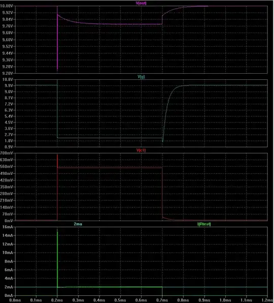
simulate this circuit – Schematic created using CircuitLab
Source: OnSemi NDS7002A datasheet (not actually the manufacturer of my part)
Edit: According to the datasheet from OnSemi, Vgs(th) seems to be at most 3 V, so I'd expect anything over that would be full on. V_TO (threshold voltage) in CircuitLab is 2.2 V.
