3

I'm trying to use a high side PFET to drive a load (50 Ω below for example, but actual case is a 200 mA motor). I know that I can use a low side NFET but that is active high, and I want to use active low in my 3.3 V TTL (with a single part). For context, I'm trying to use a PCF8574 to switch a load, which is active high at power on.

Edit: If not possible to reduce the part count, perhaps I can reduce the complexity or cost. E.g. Andyaka's suggestion in the comments to use a Zener diode.

I'm able to turn the PFET off by using an NPN to drive the gate up to 10 V, but I'd like to use a single part if possible. Being familiar with NFETs, I tried driving the PFET gate to 3.3 V, but that didn't turn the PFET off (I'm still trying to understand PFETs, hence this question). I see that you have to drive the gate all the way to 10 V to turn it off. I read the datasheet, and \$Vgs(th)\$ is -1 V to -3 V, which I don't understand.

I suppose I could also use an NFET to drive the PFET instead of the NPN below, and in this case maybe that's what a complementary PFET/NFET IC is designed for? If so, that'd reduce it to a single part. Is that the best way to keep my part count to 1 and achieve active low?

schematic

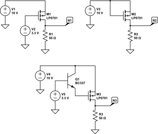
simulate this circuit – Schematic created using CircuitLab

Measurements

Nick Bolton
  • 2,043
  • 8
  • 31
  • 2
    You can't reduce your part count to 1; think again; be realistic. State what might be acceptable and you might stand a chance. You can fudge a P channel MOSFET with a drive that is in series with a zener diode but, that requires a zener diode and some resistors. Part count doesn't equal 1. – Andy aka Nov 05 '22 at 11:41
  • @Andyaka Thanks for confirming that I can't reduce the part count, that should be the answer. I'll stop barking up that tree! Edit: Perhaps I can reduce cost or complexity instead of reducing the part count? – Nick Bolton Nov 05 '22 at 11:42
  • 2
    But you can reduce the part count to one. Buy a suitable all-in-one component. These are called "power switches" and are available for both high side and low side switching, with active low or active high logic control input. Want that as an answer? – Justme Nov 05 '22 at 11:50

1 Answers1

4

You can fudge it with a zener diode like this: -

enter image description here

But you need to be careful in selecting the resistor and, it only works when the supply remains at 10 volts and your logic level is 3.3 volts. But, you might as well use an N-channel device like this: -

enter image description here

So, this time you drive the source of the N-channel device (common gate circuit). This permits you to have the input active low i.e. when the drive input is low, the P-channel MOSFET is activated.

I read the datasheet, and \$V_{GS(TH)}\$ is -1 V to -3 V, which I don't understand.

It means that the gate has to be more negative than the source to start activating a P-channel device. In comparison, for an N-channel device, the gate has to be more positive than the source to activate the device.

I suppose I could also use an NFET to drive the PFET instead of the NPN below, and in this case maybe that's what a complementary PFET/NFET IC is designed for? If so, that'd reduce it to a single part. Is that the best way to keep my part count to 1 and achieve active low?

You will still need a resistor and that makes two added components. You need at least two components added to make this work.

Nick Bolton
  • 2,043
  • 8
  • 31
Andy aka
  • 434,556
  • 28
  • 351
  • 777
  • Thanks for trying to explain negative Vgs(th), but the penny still hasn't dropped for me. Perhaps there's a chapter in Practical Electronics for Inventors or Art of Electronics that covers this? – Nick Bolton Nov 05 '22 at 12:26
  • 1
    I have no idea about books and what they may contain. Never bought books or read them. I just read data sheets and use the internet. Do you understand for an N-channel device, the gate has to be more positive than the source to activate the device? – Andy aka Nov 05 '22 at 12:28
  • > "I just read data sheets and use the internet." -- Wow, ok I need to rethink a few things. – Nick Bolton Nov 05 '22 at 12:29
  • 2
    Yeah but I've been in this business since 1975 so I've learned a lot and luckily, remembered a lot of it. – Andy aka Nov 05 '22 at 12:30
  • @NickBolton Negative threshold voltage is seen in P-channel enhancement-mode (the standard type) devices and in N-channel depletion-mode devices. Positive threshold voltage is seen in N-channel enhancement-mode devices and P-channel depletion mode devices. All the polarity means is that the threshold is when the gate is at a lower voltage than the source (for negative Vth) or when the gate is at a higher voltage than the source (for positive Vth). You can even get parts with a threshold voltage of zero. – Hearth Nov 05 '22 at 18:25
  • I wondered if your trick with the IO on the source would work for low side too, and it does... better than driving an NMOS in the conventional way: https://www.circuitlab.com/circuit/j324jg6pffux/low-side-circuit-switch/ – Nick Bolton Nov 05 '22 at 22:32
  • It's a bit scary connecting 10 V to 3.3 V like this... the body diode goes from source to drain, so I guess that's not an issue. But, can't the voltage at the drain raise the voltage at the source? Simulator seems happy, but this breaks my original understanding of FETs. – Nick Bolton Nov 05 '22 at 22:39
  • You are not connecting 10 volts to 3.3 volts; there's a pull-up resistor in the way (can be 10 kohm). This all rests on your understanding of MOSFETs and not mine @NickBolton – Andy aka Nov 06 '22 at 00:07
  • > "there's a pull-up resistor in the way" Aha, I had no idea a resistor could prevent one a higher voltage source from raising a lower source. My experience was that if you connect two voltage sources together, the higher one will pull the lower one up to the same voltage. Kind of mind blowing that a resistor can stop that happening. – Nick Bolton Nov 06 '22 at 07:38
  • > "I had no idea a resistor could prevent one a higher voltage source from raising a lower source." -- Ok, so I played around with this in CircuitLab, EveryCircuit, and an actual breadboard. Fascinatingly, all behaved a little different. The breadboard behaves how I expected; depending on the R size, it will block different levels of voltage (so, nothing new to me there), but curiously in the simulators, the voltage isn't raised on the other side of the resistor, even if the R value is very low... I suppose that's just either not worth simulating or too complex to similate? – Nick Bolton Nov 06 '22 at 09:26
  • Correction: Simulating in CircuitLab and EveryCircuit produces the same result, a current flows from the high voltage to the lower voltage source depending on the R size (e.g. with a 1k blocking resistor, if the high voltage is 10 V and the low voltage is 1V, then 9mA flows from low to high). – Nick Bolton Nov 06 '22 at 10:24
  • On the breadboard: With a 1k resistor, 4.18mA flows from the 10 V source to 1 V source, and on the side of the resistor with the 1 V source, this voltage is actually raised to 5.8 V. – Nick Bolton Nov 06 '22 at 10:28
  • Correction: > "9mA flows from low to high" -- I actually meant the opposite; the current of course flows from high to low. – Nick Bolton Nov 06 '22 at 10:31
  • This video really helped me understand the common gate circuit: https://www.youtube.com/watch?v=Fh-Xhc88P2E&ab_channel=JordanEdmunds – Nick Bolton Nov 06 '22 at 10:33
  • Also, Razavi on common gate for those who want to learn more... https://www.youtube.com/watch?v=-Gm7BskTC1A&ab_channel=LongKong – Nick Bolton Nov 06 '22 at 10:45
  • @NickBolton if the higher and lower voltage sources do not have low impedance then adding a resistor between them will pull them together noticeably. Using and N-channel in common to directly control a load is not usually done because the source input has to take the load current. – Andy aka Nov 06 '22 at 12:05