1

I wanted to update this subject as LTspice has evolved from this post: How does LTSpice model reverse recovery time?

To sum up the above post answered by Ste Kulov:

As Ste Kulov said, LTspice allows to model reverse recovery time. From the JEDEC document JESD282B.01, the reverse recovery is defined as follow :

enter image description here

Some definitions of the terms in this image:

\$I_F =\$ The forward current prior to reversal.
\$I_{RM(REC)} =\$ The maximum reverse current peak after reversal.
\$di/dt =\$ The slope of the transition from forward current to reverse current.
\$t_{rrr} =\$ The subscripts imply "reverse recovery rise" time, but this is normally called the storage time.
\$t_{rrf} =\$ The subscripts imply "reverse recovery fall" time, but this is called either transition time or transient time in various texts.
\$t_{rr} =\$ This is what you know as the reverse recovery time as specified in manufacturers' datasheets under certain conditions. It is simply the sum of \$t_{rrf}\$ and \$t_{rrr}\$.

The part which is defined as the "reverse recovery rise" time \$t_{rrr}\$ can be modeled according to the different references given by Ste Kulov: "The full derivation of this approximation is discussed in the last few pages of this PDF snip (or cached screenshot), which appears to be an excerpt from Solid State Electronic Devices by Ben G. Streetman.." To sum it up:

$$t_{rrr} = TT \cdot \text{ln} \left[ 1 - \frac{I_F}{I_{RM(REC)}} \right]$$

Where \$TT\$ is, according to LTspice, defined as the transit time:

enter image description here

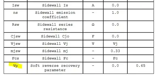
Nevertheless, the transit time does not model the "reverse recovery fall" \$t_{rrf}\$. At the end of its post Ste Kulov is saying that since LTspiceIV, LTspice allows to model it via the soft reverse recovery parameter \$Vp\$.

enter image description here

Where the documentation from LTspice gives for \$Vp\$ the following definition:

The soft reverse recovery parameter, \$Vp\$, adds a dQ/dt damping to diode charge as suggested by K.J. Teng and S. Pan in 'Modified charge-control equation for simulation of diode reverse recovery', Electronics Letters, 15th February 1996 Vol. 32 No. 4.

Nevertheless, I did not have access to this document, and I am not able to set the "reverse recovery fall" \$t_{rrf}\$ by adjusting the \$Vp\$ parameter.

I searched the NGspice documentation but it seems that NGSpice has no parameter for modelling the "reverse recovery fall".

Does anyone know what the relation is between \$Vp\$ and \$t_{rrf}\$?
ocrdu
  • 8,705
  • 21
  • 30
  • 42
Jess
  • 2,694
  • 1
  • 18
  • 46
  • 1
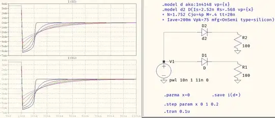
    How did you try it? It can be done in the `.model` card, with or without `ako`: https://i.stack.imgur.com/U3E1G.png. – a concerned citizen Nov 05 '22 at 13:58
  • Hi, Thank you for your comment :) I am not saying that it is not possible to simulate the "reverse recovery fall". For example, if I tested a real diode and I know its "reverse recovery fall" by measuring it, should I try several "Vp" randomly and look at what it is the "reverse recovery fall" of diode model to see if it fits with the diode tested ? It will be more appropriate to know what is the relation between Vp and the "reverse recovery fall", if it is possible – Jess Nov 05 '22 at 14:12
  • 1
    Oh, I don't think there is. You can make `vp=10` and it will still show something but, it will look hideous. I'd recommend values between `0...0.5` for quasi-realistic plots, otherwise there's no documentation explaining what `vp` does in LTspice. I also don't have access to that document, so I cant say too much, except that I *think* it's a gimmick setting (e.g. GoodEnough®). If you have to match `Tt` exactly then you may even have to adjust it, too, together with `vp`, so that the decaying doesn't exceed its setting (in the example `tt=20n` and with `vp=1` it goes well beyond the limits). – a concerned citizen Nov 05 '22 at 14:27
  • Ok thank you for your help :) Do you know how the manufacturer of semiconductors does to model a diode for example if there is no explicite relation ? I saw that most of the diodes included by default into LTspice does not have a Vp parameter. – Jess Nov 05 '22 at 15:03
  • I may do an other post for this question. There is so many parameters to model a diode into LTspice ... And it is just a diode x) – Jess Nov 05 '22 at 15:06
  • 1
    The `vp` parameter was not there since the beginning, it was added ...uff, I don't know, up to 10 years ago (?, not sure), it's not even in the `Changelog.txt`. It's certainly not a generic SPICE parameter, so it's very possible that many (read: the overwhelming majority) will not have, and maybe not even know about `vp`. It's easy to add, though, with te `ako` (see the example). – a concerned citizen Nov 05 '22 at 15:07
  • I agree with you. Thank you for your help :) – Jess Nov 05 '22 at 15:09
  • 1
    If you google "ngspice vp", one of the top results is a big discussion regarding this Vp parameter, including the equations from the $33 paper along with my (failed) attempts of implementing the equation within ngspice: https://sourceforge.net/p/ngspice/feature-requests/76/ . You have to scroll down a bit to where I attach the equation images since they got removed from the first post. Also one of the attachments is the test circuit (diode_rr.cir) I used for my tests. You should delete or comment out the the `.save` statements so you can more easily plot the diode current in LTspice. – Ste Kulov Nov 06 '22 at 06:57
  • Thank you for all your documentation :) I will take a look on it :) – Jess Nov 06 '22 at 09:34

1 Answers1

2

I don't think there is any relation other than an afterthought (some 10 years ago, ±5, more - than +), where Mike added the parameter, possibly as a GoodEnough® setting for tinkering (e.g. a "gimmick"). It's not mentioned in the help and not even in the Changelog.txt (of either LTspice IV or XVII). You can make vp=10 and it will still show something but, it will look hideous. I'd recommend values between 0...0.5 for quasi-realistic plots, otherwise there's no documentation explaining what vp does in LTspice. I also don't have access to that document, so I cant say too much. If you have to match Tt exactly then you may even have to adjust it, too, together with vp, so that the decaying doesn't exceed its setting (in the example tt=20n and with vp=1 it goes well beyond the limits).

two ways of using it

a concerned citizen
  • 21,167
  • 1
  • 20
  • 40
  • ...but if someone else knows better, I'd be glad to correct my views. – a concerned citizen Nov 05 '22 at 15:12
  • 1
    A big discussion along with the equations found in the IEEE paper [can be found here](https://sourceforge.net/p/ngspice/feature-requests/76/). Also, there is more info regarding the differences in `Vp` between LTspiceIV and LTspiceXVII [in this message](https://groups.io/g/LTspice/message/126793) and subsequent messages [in the same topic](https://groups.io/g/LTspice/topic/77407536). Lastly, I just wanted to confirm that there is no direct calculation to map \$t_{rrf}\$ to `Vp`. I concur that it is done empirically by matching bench measurements to simulation results of various `TT` and `Vp`. – Ste Kulov Nov 06 '22 at 07:07
  • 2
    @SteKulov Yes, I remember the thread. How can one not remember when the result of so much discussion ends up with the mysterious parameter in question to become even more mysterious? :-) And the one on sf.net shows that the difference is a simple addition of a derivative. Funny enough, your 1st stab resembles LTspice IV's shapes. Personally, I use the `vp` like this: if it's a fast diode (e.g. `1N4148`) then I use `vp=0.2...0.3`, and it it's a slow diode (e.g. `1N400x`) then I use `vp=0.4...0.5`, no more (the "dip" is affected too much). Empirical FTW. – a concerned citizen Nov 06 '22 at 08:39
  • Thank you so much for all this documentation :) I will take a look on it ! – Jess Nov 06 '22 at 09:32