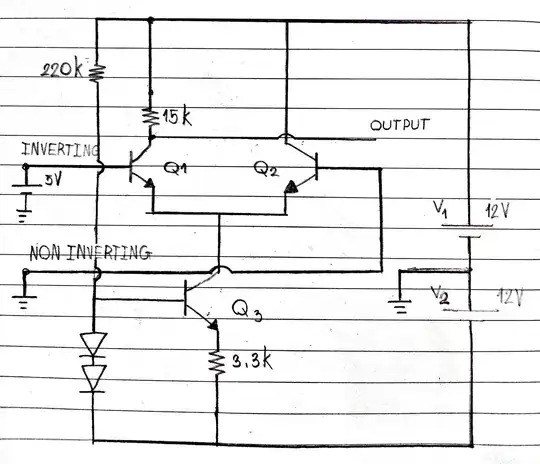
Let's first remove some of the clutter in your schematic:

simulate this circuit – Schematic created using CircuitLab
Mostly, all I did was to remove some wiring that bused around the power rails. There's usually no need for drawing all those wires (unless it is supposed to be a construction diagram.) For understanding, though, the wiring isn't needed. It's enough to just know the rail names and keep them localized to the area where they are being used.
To start, when the ( - ) input is left floating while the ( + ) input is driven by some ideal voltage source, \$Q_1\$ will receive no observable base recombination current so, in theory, there should be no collector or emitter current. So, ideally, it would be as if \$Q_1\$ were removed and the hole it once filled left open (not shorted.) So \$V_{_\text{OUT}}=15\:\text{V}\$, when unloaded, and all of \$Q_3\$'s sinking collector current just passing through the sourcing \$Q_2\$'s emitter. \$Q_2\$ should be in active mode so long as the ( + ) input isn't raised above \$V_{_\text{CC}}\$.
There's a term for \$Q_2\$ in this case -- a cascode. There's an Early Effect operating with \$Q_3\$. But when \$Q_2\$'s base is grounded, then its emitter will be a diode drop below ground and it will stay there. So the \$V_{_\text{CE}}\$ of \$Q_3\$ will be fixed and not changing. So whatever Early Effect is operating on \$Q_3\$ won't vary. In effect, \$Q_2\$'s collector current is driven by \$Q_3\$ and \$Q_3\$ won't vary its collector current due to the Early Effect, thereby allowing \$Q_2\$ to pass along this current to its collector to some collector load without an Early Effect impacting \$Q_2\$'s collector current since it is set by a different BJT (\$Q_3\$.) In this circuit, all that doesn't mean much. But it is much more important in other circuits. So it's something to stick in your mind and keep track of, which is why I bothered writing this.
In your second case, where ( + ) remains nailed to ground, you added an ideal voltage source of \$+5\:\text{V}\$ to ( - ). Now, you should be able to see that this means \$Q_1\$'s emitter cannot be much more than one diode drop below this, or at about \$+4.3\:\text{V}\$. (Keep in mind that each \$60\:\text{mV}\$ change in the base-emitter voltage of a BJT there is a 10X change in its collector current. So it's not likely to be much different than somewhere between \$+4.2\:\text{V}\$ to \$+4.4\:\text{V}\$.) But this means that \$Q_2\$'s emitter is also set at that voltage, which is well above its base voltage at ( + ). So \$Q_2\$ turns off.
You might think that \$Q_2\$'s emitter should be at \$-0.7\:\text{V}\$. But I'm sure you can see that both emitters are tied together by a wire. So this wire cannot be both \$+4.3\:\text{V}\$ and also \$-0.7\:\text{V}\$. That just doesn't fly. It turns out that because of this 10X factor of collector current change for each \$60\:\text{mV}\$ change in the base-emitter voltage of a BJT, that \$Q_1\$ will very quickly wind up sourcing all of the current into \$Q_3\$'s collector, leaving \$Q_2\$ with nothing left to do. So that's why \$Q_2\$ is the one to shut off and not \$Q_1\$, in this case.

