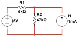
I gather you find the correct answer from this transformation:
simulate this circuit – Schematic created using CircuitLab
One way to see why is that the transformation on the left side doesn't change the circuit on the right side and the voltage difference across \$R_2\$ remains unchanged. \$I_{_{\text{R}_2}}\$ is outside of the change. So you can use usual methods to work out the current in \$R_2\$. Which you did do.
Of course, now there is a question of what happened here to \$I_{_{\text{R}_1}}\$. But since you weren't interested in that, it doesn't really matter.
In this transformation, though:
simulate this circuit
There is now your question about \$I_{_{\text{R}_2}}\$ and what happened to it. In this case, it was impacted by your transformation!
So how can we recover it?
Well, one thing you can observe here is that \$I_{_{\text{R}_1}}\$ wasn't changed, this time. It's still the same value as it was before the transition. So the current you computed here represents \$I_{_{\text{R}_1}}\$'s magnitude. It must! That fact was not lost during the transformation.
You would compute \$I_{_{\text{R}_1}}=\frac{5\:\text{V}-47\:\text{V}}{5\:\text{k}\Omega+47\:\text{k}\Omega}=-807.69231\:\mu\text{A}\$. (It's pointing opposite our indicated arrow.)
So let's return to the initial schematic you started with:
simulate this circuit
Well, now this is pretty easy. It's pretty clear that \$I_{_{\text{R}_2}}\$ must be the sum of \$I_{_{\text{R}_1}}\$ and \$I_1\$. So:
$$I_{_{\text{R}_2}}=I_1+I_{_{\text{R}_1}}=1\:\text{mA}+\left(-807.69231\:\mu\text{A}\right)=192.30769\:\mu\text{A}$$
So there it is. Recovered.
Both methods work. You just need to keep your eye on the ball. That's all.
