I think you've assumed that the negative power supply potential to the op-amp is 0V. This circuit can only work when the negative supply potential to the op-amp is, well, negative. In other words, you need a dual supply, such as +12V and -12V for this circuit to work.
If the op-amp's negative supply potential is 0V, the lowest output you can have from the op-amp is zero volts, which has the following consequences:
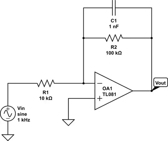
When the op-amp output is zero volts (\$V_O = 0\$), the potential divider formed by R1 and R2 present 0V to the non-inverting input, so \$V_P = 0\$
When the op-amp output is zero volts (\$V_O = 0\$), the inverting input (derived from C and Rf) can never fall below 0V either. Therefore the inverting input cannot ever fall below the inverting input in potential. Always \$V_N \ge V_P\$
In other words, you seem to have identified a potential problem (pun completely intended). Once the output falls low (0V), the circuit is stuck in that state.
The only way this circuit can oscillate is if the op-amp's output is permitted to become negative, and the only way that can happen is if the op-amp's negative supply potential is negative.
Edit
It's possible to modify this circuit to operate from a single-ended supply, by biasing the op-amp's feedback potentials. The idea is to raise the two switching threshold potentials so that they sit above and below half of the supply voltage. The lower threshold is then well above zero, allowing the the junction of C and Rf to swing below it, something that it can't do in the existing setup.
simulate this circuit – Schematic created using CircuitLab
Here R1 and R2 have changed role. They now provide a potential half way between the supplies, at +2.5V. R3 allows the op-amp output to modulate that value somewhat. The simplest way to understand this is by replacing the combination of the +5V source, R1 and R2 (boxed in blue) with their Thévenin equivalent:
simulate this circuit
Now it becomes clear that as the output switches between +5V and 0V, the potential divider formed by Rth and R3 applies feedback with some fraction of the amplitude of that oscillation (one half in this example, since Rth = R3), centered about +2.5V.
With the values shown, and assuming the op-amp output is rail-to-rail, the two threshold values will be \$V_P = +2.5 \pm \frac{2.5}{2}\$, or \$V_P = 3.75, 1.25\$


