If OA2 is an ideal op-amp (no input bias currents) then the voltage at the non-inverting input is:
$$V_{+} = \bigg(\frac{V_{IN+}}{R3} + \frac{0}{R4}\bigg)\bigg(R3||R4\bigg) = V_{IN+} \cdot \frac{R4}{(R3+R4)}$$ ..a voltage divider.. and it is unaffected by the op-amp output. Where
$$R3||R4 = \frac{1}{(1/R3 + 1/R4)} $$
Similarly, the voltage at the inverting input is:
$$V_{-} = \bigg(\frac{V_{IN-}}{R2} + \frac{V_{OUT}}{R1}\bigg)(R1||R2)$$
If you don't understand the above, best stop until you do. These are just voltage divider equations you can write down by inspection.
Note that one of the two voltages (\$V_{-}\$) is a function of one of the input voltages and the output, and the other is only a function of the other input voltage.
If the op-amp has finite gain \$A_{0}\$ then
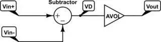
$$Vout = A_{0}((V_{+}) - (V_{-})) $$
So increasing the input voltage \$V_{IN+}\$ tends to drive the output positive, and increasing the input voltage \$V_{IN-}\$ tends to drive the output negative. Increasing the output voltage tends to drive the output negative (so we have net negative feedback, an important observation).
In the case where \$A_0\$ tends to infinity, and there is net negative feedback, and the output is unconstrained by real-world limits such as supply voltages, maximum currents etc., we can say that the difference between V+ and V- will approach zero volts. At DC that's a very good approximation for a modern precision op-amp.
So we we equate V+ and V- we get:
$$k_1 V_{IN+} = k_2 V_{IN-} + k_3 V_{OUT} $$
Or:
$$V_{OUT} = (k_1/k_3) V_{IN+} - (k_2/k_3) V_{IN-} $$
Where \$k_1/k_3\$ and \$k_2/k_3\$ are fixed constants that depend on the resistor ratios.
In the case where \$R1=R2=R3=R4\$ (or just R1=R2 and R3=R4), the output voltage is just the difference between the two input voltages.
$$V_{OUT} = V_{IN+} - V_{IN-} $$
In general though
$$V_{OUT} = \frac{R4(R1+R2)}{R2(R3+R4)}V_{IN+} - (R1/R2) V_{IN-} $$
As an aside, note that your first circuit does not really act as an amplifier if ideal voltage sources are applied to the inputs. The voltage at the inverting input will not change with the output voltage, so there is no feedback at all. The output will just slam from one rail to the other depending on the polarity of the difference in voltage. If you apply a current rather than a voltage (maybe from a reverse-biased photodiode detector) to the inverting input then you have a transimpedance amplifier where the output voltage is proportional to the negative of the input current.