I'm trying to make a headset with microphone (and stereo audio) for an Android phone. The headset will be connected to a 3.5 mm TRRS jack. I have read the specifications for such devices from Android Source. My schematic with working buttons is:

simulate this circuit – Schematic created using CircuitLab
The "mic" resistor is the dummy microphone I used before I received the real microphone (real microphone's output impedance is 2.2 kΩ). I have named the switches according to the functions A...D and calculated their corresponding resistances based on the equations from Android Source (the values shown in the schematic are measured resistances.) This schematic works and I get pushed buttons to work as described: Answer call, volume up/down and "voice control".
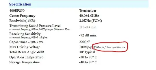
The problem comes when I added the real microphone (mic specs) and removed the dummy resistor. New schematic:

For the microphone connections, I used the schematic ("measurement circuit") provided in the microphone data sheet.
- After adding the microphone to the circuit, all the buttons stopped working but the microphone works.
- If I added the 2.2 kΩ dummy microphone to the circuit with the real microphone, the buttons start working but the microphone stops working or at least no sound comes from the speaker. (Maybe not enough current?)
- I have tried removing capacitor C1 with the dummy "mic" and just connected microphone straight to MIC-line and removed the external bias voltage and R5. The buttons work, microphone doesn't.
I have measured the microphone to ground (microphone bias voltage?) voltage of my phone and it is only 0.825 V instead of the 1.8-2.9 V specified at Android Source, for some reason, but I do provide the external bias voltage for the microphone.
The speaker I used is just some 32 Ω cut from a handsfree ear button set.
Is this something obvious that I'm missing here? Would I just need some amplification of the microphone with an op amp to get it working with the buttons even if the sound is loud enough without the buttons working?
I do have some low power op amps coming but would like to know if there is something else in my circuit that is the fault here.
EDIT: Actually, my phone gives out 1.77 V after it has detected microphone and then removed the load and measured. The other phone gives constant 1.77 V all the time even without previous detection of load.
Found the problem, it was latching button. The buttons I bought should have been non-latching but doesn't seem so. So the hardware buttons can't be pressed at the same time when using the microphone at least with this schematic. I wonder how they make those PTT headsets work?
