3

I'm using a 74LS137 to drive a 7 segment LED (common anode.) Since it's a sink, it "inverts the demux outputs" as desired:

LED with 74137 output as sink

I want to wire-OR two outputs, but you can't do so directly for 74LS137 (correct?) so I need diodes:

two outputs with diodes to sink LED

Doing so reduces the brightness of this segment, so I'll add a transistor, but if I use an NPN I will "lose" the inversion:

LED with NPN driver, base at two diodes

Note I can't change R1 & LED, because it's a common anode display. Can I use a PNP transistor? The following seems wrong. Can it be made right?

LED with PNP driver, likely wrong

I'd really like a single transistor solution if possible.

JRE
  • 67,678
  • 8
  • 104
  • 179
John H.
  • 141
  • 5
  • Did you try re-calculating the resistor based on the extra voltage lost to the diode? – user253751 Oct 20 '22 at 19:38
  • @user253751 Currently the resistor is common to all the segments. I could use a separate resistor per segment, but I'm trying to avoid that. – John H. Oct 20 '22 at 19:41
  • You could put a diode in series with each output - even the ones which don't need it. – user253751 Oct 20 '22 at 19:42
  • @user253751 Minimum part count is "important" here. – John H. Oct 20 '22 at 19:46
  • I take it you don't want to use a common cathode display (which would allow you to use the PNP between the rail and the LEDs). There are single OR gates in a SOT-23 package that have enough sink capacity to run a LED. This seems a bit like it might be an XY problem though; why are you using a 74LS137 to drive the display and not e.g. a 74LS47? – vir Oct 20 '22 at 19:53
  • "Currently the resistor is common to all the segments" - which means the display brightness will vary according to how many segments are lit. Resistors are cheap and tiny. – Finbarr Oct 20 '22 at 19:59
  • 74137 is 8-3 demux, so only one output is active (low) at a time. – John H. Oct 20 '22 at 20:03
  • I think we could make more informed recommendations if we knew something about the rest of the circuit. – vir Oct 20 '22 at 20:05
  • Only 1 output of 74137 is active at a time. And yes, this is what I want :-) – John H. Oct 20 '22 at 20:05
  • This PNP idea won't provide full brightness, by the way, because it's an emitter follower circuit. – user253751 Oct 20 '22 at 20:06
  • Minimum part count is a microcontroller that connects directly the each segment. – user253751 Oct 20 '22 at 20:16
  • @JohnH. Try your wire-or version but using Schottky diodes for their low forward voltage drop. The difference in brightness between the segments may be imperceptible. –  Oct 20 '22 at 21:53
  • @James That's a great idea, thanks! – John H. Oct 21 '22 at 01:23

6 Answers6

2

You can use a common base configuration. Must be two transistors though. Can't be done with only one.

schematic

simulate this circuit – Schematic created using CircuitLab

RussellH
  • 12,496
  • 2
  • 9
  • 34
2

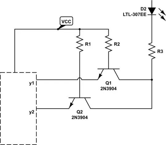
Due to the common anode, you're forced to place the switching element (the transistor) on the cathode side of the LED, low-side. This means that any PNP (or P-channel FET) will be operating as a voltage follower, which will always incur an additional loss of \$V_{BE}\$ (or \$V_{GS}\$) across the transistor.

An emitter (or source) follower configuration is the only way you can achieve non-inverting behaviour from a single transistor, so sadly I don't think you'll find a single transistor solution that doesn't suffer from that loss.

I would suggest that you try using a CMOS IC, like the 74HC137, rather than the 74LS137. If there's anything else sinking current from an LS output, a high is not guaranteed to be above +2.4V, which might not be high enough to switch the LED completely off! An 'HC device has CMOS outputs which will get very close to both supply potentials.

I imagine you've already considered this, but I'll say it for completeness: a discrete transistor solution is still going to require space for a couple of diodes and a transistor, which is already approaching the footprint of a single 14-pin IC. The solution might simply be to use a 74'08, 74'11 or similar. That way you have no diode voltage drops to worry about, and a bunch of spare gates. A more useful IC might be a 74'00 or 74'10, it's always useful to have a spare inverter.

Simon Fitch
  • 27,759
  • 2
  • 16
  • 87
1

Using a PNP transistor presents other problems. To maximize the brightness, you will want to saturate the transistor. In saturation, the voltage from the emitter to the collector is lower than the voltage from the emitter to the base. Since the collector is at ground, the base can not achieve a lower voltage from the driver chip. This would be further compounded by the voltage drop in the diodes in series with the base.

You can do it with two transistors: one pnp and one npn. I don't know how to enter a circuit diagram, so I'll try to describe it:

The anodes of the two diodes connect with the base of a pnp transistor, which is pulled up to Vcc with a 20k resistor. The pnp emitter is connected to Vcc through a 4.7k resistor. The collector of the pnp is connected to the base of the npn, and pulled down to Gnd with a 20k resistor. The emitter of the npn is connected to Gnd. The collector of the npn is connected to your display segment.

When the two diode cathodes are high, the pnp is off, and the npn is off. When one or two of the diode cathodes is low, the pnp is saturated on. The pnp emitter resistor limits the current to about 1 ma, which flows into the base of the npn. The base current turns on the npn in saturation, giving a bright readout.

cmm
  • 419
  • 5
  • 8
1

I believe this is the two transistor answer from @cmm:

schematic

simulate this circuit – Schematic created using CircuitLab

John H.
  • 141
  • 5
0

With TTL (such as 74LS... parts) you can just "wire or" the outputs

Actually it's usually called "wire and", but since you're using negative logic it becomes a "wire or".

  • 1
    That's true for parts with open collectors, but not all 74LS have open collectors -- eg, 74LS137. The datasheet says "don't short circuit the outputs more than one second." Am I missing something? – John H. Oct 21 '22 at 17:46
0

@james suggested "using Schottky diodes for their low forward voltage drop. The difference in brightness between the segments may be imperceptible."

John H.
  • 141
  • 5