In general yes the error can be zero.
Take a tracking system, for example, a system that controls the angular position of an antenna by comparing the voltages across a potentiometer attached to the antenna and another potentiometer that gives the set point.
Source: Stefani's book
It's an example that is made in many control theory books (for example Stefani, "Design of feedback control systems 4e", p.92, or Dorf, "Modern control systems 10e", p. 282, or in the introductory chapter of Nise,"Control systems engineering").
 Source: ResearchGate
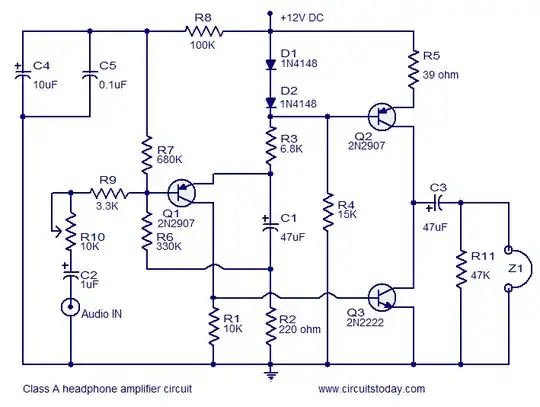
"Figure 1 is the control block diagram of the DC servomotor antenna pointing system (Nise, N.S., 2011). The
first input to the summer is set position)(tr, the desired position at which the azimuth or elevation motor is
expected to run to. The second input is the feedback signal, the current position of the respective motor,
captured by some feedback sensor like the potentiometer and changed to a summer readable format. The
difference between these two inputs, called position error signal)(te, is given to the controller that reads the
error signal and produces appropriate output signal, controller output)(tu.The controller output then reaches
the motor driver, which produces a proportional output to rotate the respective motor in either direction
according to the sign of the error signal (positive or negative). As the desired position is approached, the
error signal reduces to zero and the motor stops (Ogata, K., 2010)."
When the antenna is in the set position, the motor that makes it turn should not be powered. In this case the error must be zero. Nise stresses this point:
"The system normally operates to drive the error to zero. When the input and output match, the error will be zero, and the motor will not turn. Thus, the motor is driven only when the output and input do not match. The greater the difference between input and output, the larger the motor input voltage, and the faster the motor will turn."
Note the difference with what happens in an electronic feedback amplifier, for example with a real op amp: a nonzero error is required to have an output that is many times the input signal. The output of the system is not zero, but a magnified replica of the input, and with zero voltage difference deltaV at the op amp terminals you won't have any output. The case deltaV=0 is a limit condition that follows when the open loop plification goes to infinity. One could say that the goal of the feedback amplifier is to alter the open loop amplification and a nonzero error is required in any real practical case.
In the case of the above tracking system, the goal is to drive the error to zero. You don't need a lot of amplification, unless you want to make the antenna absolutely unmovable.
Regarding steady-state errors.
In most control textbooks you will also find a table showing the value of the steady state error for different inputs (step, ramp, parabolic) applied to systems of different orders. This error can be zero from type 1 onward, depending on the type of input.
 Source: Stefani's book
Note that in the above table A is a coefficient in the input. The amplification is rather identifiable with the K coefficients, and the bigger K the lower the nonzero steady-state error becomes. But for some systems and input, the steady-state error is exactly zero.
What counts is the presence of as many integrations as the system's type.
As a matter of fact, on Dorf the steady state error of a PID system with disturbance and noise is analyzed (it's a medical pressure control system) and it is shown that as long as the constant Ki is non zero, the steady state error for the step response of that system goes to zero. (It's on page 249 on the 13th edition.)
Regarding noise.
Some systems reject fairly well noise in the plant or in the feedback loop. Of course, if you add noise to the error signal itself, then you might argue the the error is not exactly zero. But then we can argue that there is no such thing as any exact value of voltage or current, and I don't think that is a useful position.


