2

Say I have a distribution board where 220VAC comes in and goes into a 220VAC-24DC converter. 24V DC is subsequently fed into a KNX-driven RGBW dimmer which powers a LED strip directly along a 5x1.5 cable (distance of about 5 meters). In fact, the RGBW dimmer acts as a de facto contactor for the converter: if the LED strip is powered, the converter is powered; if the LED strip is not powered, the converter is subsequently not powered. This means the live wire goes into the dimmer, then out to the converter.

My question: do I need a circuit breaker anywhere along this path? Given that LEDs spike at startup, how do I calculate what breaker I need? For example, say I need a breaker for a 150W peak AC-DC converter that feeds 100W of LEDs, should I be going for a 10A type C breaker or something else?

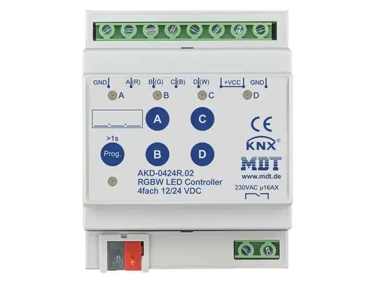
Clarification about the dimmer being a contactor. I've included a picture below to illustrate. The bottom right hand contacts are a breakable circuit path which is only activated when the dimmer is instructed to shine something. Thus, the path of the live wire in the circuit goes like this:

Input -> RGBW contactor in -> RGBW contactor out -> 220-24

Then, assuming the AC-DC converter is powered, the 24V output is then fed into the top contacts of the dimmer, which in turn distributes this energy to the RGBW contacts.
enter image description here

Dmitri Nesteruk
  • 474
  • 2
  • 16

2 Answers2

2

you need no breaker other than what the supply wiring and the AC-DC converters require.

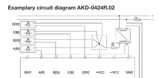
enter image description here

See 16A fuse top right in example wiring diagram.

2

I see where this is a special RGBW dimmer which has an auxiliary contactor rated 16A or 230VAC, and it communicates via networking (KNX) for all controls including control of that contactor.

Using that as the power switch for the 220VAC->24VDC converter isn't going to work. Well, you'll be able to turn off the DC power supply via KNX. But having done so, it will have "swept the rug out from under its own feet", thus denying power to itself, so it will not be able to respond to any command to turn the contactor on.

So it would work as a "self-kill" safety feature, but not as a routine on/off device. You'll need an alternate way to inject 12/24V to power it up, get it listening and get it to pull in the contactor.

Note that if your electrical codes are requiring a disconnect switch for the power supply, that will not suffice. However since you have DIN rail there anyway, just fit a conventional circuit breaker.

I see no need for RCD other than the main RCD on your utility supply. 24 volts is not lethal and does not warrant RCD protection. Further, RCD has a problem with DC. If DC current leaks through an RCD, it will saturate the core of the sense transformer, which will render the RCD unable to detect AC leakage voltage as intended. It's a tricky problem, especially with electric vehicle charging.


Other than the contactor, this RGBW dimmer is entirely a 12/24V DC animal (it works on either voltage without modification). It inputs:

  • 0V power (common)
  • -24V power
  • a control input, KNX in this case

And outputs

  • 0V (common)
  • -24V which is PWM modulated for RED
  • -24V which is PWM modulated for GREEN
  • -24V which is PWM modulated for BLUE
  • -24V which is PWM modulated for WHITE

Or a couple other configurations as discussed in the manual.

This either directly powers the LEDs, or is used as pilot signal to an amplifier. Or both.

Did you catch where the common/0V point is the positive wire on the 24V supply? That's right, most LED strips are positive common aka common-anode.