Using the results from a previous question i want to implement a squaring circuit. This circuit was posted by some other user in the answers.
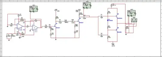
Below is an image of the squaring circuit used. I have to supply negative voltage to the op amps VEE to make it work so i used a negative voltage charge pump using a square wave to be able to supply that voltage. I also have to keep in mind that the op amps used have a maximum supply voltage of 7 volts.
Vee doesnt seem to be so well behaved when it is connected to the square circuit, for some reason it goes to -30V.
In comparison this is how that curve was when there was no square circuit attached to it (and in the breadboard where i tested this i got -2V):
The output seems to be right even though Vee has around -30V:
It took LTSpice a few seconds to get it ready to simulate, it took a lot of iterations.
I tried to implement this on a breadboard.
The square wave, Vcc (5V), 1V supply and input signal will be generated by an ESP32 microcontroller. I use the same values for resistors/capacitors that were shown in LTSpice here.
The Breadboard where the microcontroller is attached it's where the squaring circuit is implemented, the other breadboard has the negative voltage charge pump where it uses a square wave output from the microcontroller.
I used arduino IDE to program the microcontroller:
As some other used pointed out, i could use the pulse width modulation functions of the ESP32 but for now i will just use delayMicroseconds functions. I tried with a bunch of values inside that function delayMicroseconds but i kept getting almost the same problems that will be shown below.
So i measured the voltage at Vee. It is -1.23V, it's not even close to those big values that i get in LTSpice so atleast i dont have to worry about the op amps supply voltage getting over its limit... :
I measured the input signal, 1.15 V. It was what i expected.
Then the output, 0.25V. Makes no sense since 1.15*1.15 = 1.3225.
I have no idea what's going on. If i change the frequency of the square wave to bigger values the Vee voltage gets lower (around -0.8V) and because of that i always get 0V at the output.

