5

I'm designing a couple of PCBs to send data and be powered over Ethernet, however, I am not entirely sure what to connect to the center taps.

I've heard different suggestions, from connecting it to 3.3 V to isolating them and connecting them to ground with a cap.

If it's relevant, I'm using the W5500 Ethernet controller

Any advice would be much appreciated.

Data sheet for connector:

Relevant screenshot from data sheet

winny
  • 13,064
  • 6
  • 46
  • 63
Cole Weber
  • 53
  • 4
  • 1
    The safest bet is always to follow the guidelines or any reference design for the specific PHY that you will be using. – Klas-Kenny Oct 03 '22 at 19:35
  • Have you looked at the [W5500 reference schematic](https://docs.wiznet.io/Product/iEthernet/W5500/ref-schematic)? – brhans Oct 03 '22 at 19:39
  • 1
    I've looked at the W5500 reference, but I didn't see any reference that included POE. Would that affect the center taps? – Cole Weber Oct 03 '22 at 19:47
  • Which center taps you even mean, the PHY side taps, or the cable side taps? – Justme Oct 04 '22 at 04:44

5 Answers5

9

The basic way PoE works is there is a pair of transformers on each end.

On the end that sends power (PSE - Power Sourcing Equipment) the secondary of the transformers are center tapped and voltage is applied positive to one transformer's center tap, negative to the other's. This way there is a DC voltage from one pair to the other.

On the end receiving power (PD - Powered Device) the transformers have center taps on the primary side and the voltage is taken from these.

By feeding the power through the center taps of transformers it keeps the power circuit from loading down the data. The DC voltage is connected common mode while the signal is connected differential mode. This is similar to how a transformer coupled audio amplifier works, the power to the output devices is connected to the center tap of the transformer.

schematic

simulate this circuit – Schematic created using CircuitLab

Another way to get PoE is to use unused cable pairs for the power.

That's the simple explanation, there's more involved such as sensing and negotiation to control the voltage depending on the equipment's needs.

GodJihyo
  • 17,628
  • 1
  • 16
  • 45
  • @ColeWeber I added a little more at the end. I would suggest doing some further reading as there are things to consider regarding safety. – GodJihyo Oct 03 '22 at 20:46
  • @GodJihyo Why doesn’t the dc saturate the transformer core? – relayman357 Oct 03 '22 at 21:12
  • 2
    Because the flux in the top half and bottom half of the transformer in GodJihyo's diagram cancel. So the net magnetization is zero, or close to it. – SteveSh Oct 03 '22 at 21:19
  • OP isn’t asking about PoE. Your answer misses a key detail about this controller: that it’s *current mode* and so needs a voltage connected to the TX side center tap. – hacktastical Oct 03 '22 at 21:32
  • @hacktastical Ah, I got thrown off by the mention of PoE in his comment and tag. – GodJihyo Oct 03 '22 at 21:38
  • Thanks, that makes sense as long as the parallel paths (twisted pair) are close in R. – relayman357 Oct 03 '22 at 21:41
  • 2
    " send data and be powered " sounds like he is asking about POE to me. – Peter Green Oct 04 '22 at 17:58
  • @PeterGreen: He's definitely talking about transferring power over an ethernet cable. May or may not be the standardized scheme named "Power over Ethernet" – Ben Voigt Oct 04 '22 at 21:41
4

Ethernet transformers may be center-tapped on the device-side, the cable side or both.

Connection of the device-side center taps varies. Some controllers leave them floating while others use them to apply a bias voltage on receive and a current path on transmit.

The cable-side center taps are used for power over Ethernet. They are usually connected to an extended diode bridge and the output of that extended diode bridge is connected to your POE controller. Pairs that are only used for power and not for data can be shorted out instead of using a center-tapped transformer.

Your jack is designed for POE with 10/100 Ethernet where two of the pairs are used for data and two are not used for data (but may be used for POE).

P5 and P8 are the cable side center taps and P9 and P10 are the shorted-out unused pairs. These four pins should be connected to an extended bridge rectifier which should in turn be connected to your POE controller.

P4 and P7 are the device side center taps. These should be connected according to the recommendations for your Ethernet controller.

Peter Green
  • 21,158
  • 1
  • 38
  • 76
4

The W5500 reference schematic reveals that this device is a ‘current mode’ type of Ethernet controller which requires a device-side center tap connected to a voltage, while the wire-side requires termination.

Here it is:

enter image description here

From here: https://docs.wiznet.io/Product/iEthernet/W5500/ref-schematic

And note the connections:

  • The TX device-side CT terminates to 3.3V. This provides a current source for the TX DAC.
  • The RX device-side CT terminates to a capacitor, midpoint-biased from the inputs (note the DC blocking caps.)
  • The TX and RX field-wire side CTs tie to the Bob Smith termination.

Power Insertion

The power insertion standard for Ethernet is called Power over Ethernet, or PoE. In a nutshell, a DC voltage is overlaid onto two or four pairs of field wires to supply power to field peripherals. It’s part of the 802.3 family of standards, and depending on version it supports power levels from 15 to 90W. More here: https://www.versatek.com/what-is-power-over-ethernet/

What are your basic requirements to support PoE? First, you will need magnetics that can handle it: the internal coil wiring needs to be larger to handle the PoE current. In your case it also needs to be a type for a current-mode PHY.

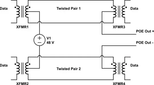
The PoE injection points are the wire-side center taps. This is the preferred approach as it only requires two pairs. It’s called ‘Alternative A’ in the PoE standards.

You also have the option to inject power on an unused pair, which might make your life easier. This is called ‘Alternative B’.

Some versions of PoE use both the active and unused pairs for higher power. Examples include camaras with pan/tilt motors.

Whichever version and power level you choose, PoE power is 48V DC. This high-ish voltage is chosen to help overcome the I-R drop in a long cable. It requires conversion circuits at each end, at the power source and at the power sink.

PoE converter technology is available from from the usual sources (TI, Linear, MPS, etc.) Typically these converters step up/down from/to a lower voltage, commonly 12V. At the power sink side you would convert the 12V to your local power rails.

Sounds like a lot of work, doesn’t it? It is, but done right (that is, compliant with the PoE standard) it’s a great boon to system installers, making it worth the trouble.

On the other hand, if your volumes are low and your platform very cost-sensitive, you have an option that may make more economic sense: use a PoE inserter. Then you don’t have to do anything different for your magnetics or local power.

hacktastical
  • 49,832
  • 2
  • 47
  • 138
2

Different transformer types can be used, these are the typical transformer configurations that can be bought. Follow the recommendations of the phy for the best type that will work for your application.

The transformer is a very important element in determining the LAN analog interface characteristics required by the IEEE 802.3 specification. The considerations for the transformer and associated input and output circuit design controlling the rise and fall time of the signal, maintaining waveform integrity and low percentage of droop for low frequencies, and designing for low inter-winding capacitance to achieve optimal CM rejection. The optimizing transformer leakage inductance and inter-winding capacitance are also used to control the frequency bandwidth and high or low rejection at desired frequencies. Figure 1 below are typical schematics of ICM module

enter image description here Source: https://www.belfuse.com/resources/applicationnotes/magneticsolutions/app-note-MAG-EMI-and-bel-magnetic-ICM.pdf

Voltage Spike
  • 75,799
  • 36
  • 80
  • 208
1

I'm using the W5500 and PoE in a current project. I have connected the Ethernet Transformer like the following. This setup is tested works in practice for me. Connection of the Ethernet Transformer / Magnetic Data line termination at the PHY

The PoE_xy connections are the +-48V going to a PoE module / DC-DC converter.

11011100
  • 331
  • 1
  • 5