0

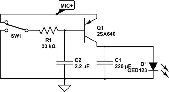
I am attempting to design an analog circuit similar to this circuit

My goal is to make it so when the SPST is closed (connected), the microphone line is 'live'. When the SPST is open, the microphone line is muted.

I currently am able to reproduce this circuit in my breadboard, however the logic is inverted (open switch = unmuted, closed switch = muted).

Solution 1

enter image description here

enter image description here

Solution 2

I've also tried this very similar circuit. While it effectively does mutes the same way, the logic is inverted so that it only mutes when the switch is closed.

enter image description here

enter image description here

Solution 3

I have tried using just a SPST switch, however there is a loud pop when connecting/disconnecting.

I have tried connecting a 100k resistor and the capacitors in parallel with the SPST switch, however that causes no audio to be delivered (and may be damaging my laptop since I have to unplug/replug in the audio to get audio working again).


I am an amateur and I've been trying to solve this problem for several days now. How can I invert the logic so that the system is muted when the switch is 'open', and the microphone is live when the switch is 'closed'. Any guidance appreciated.

Research I've done

Update: It seems there may be better circuits to mute a circuit. See this blog

Also there are dedicated chips like MAX9890 to eliminate pops

spuder
  • 399
  • 3
  • 14
  • 1
    You are putting the switch in parallel so of course it will short out the mic when closed and unmutes when open. Have you tried putting the switch in series like how light switches are for lamps? Open switch and mic equals unplugged, close switch and mic equals plugged. – Justme Oct 01 '22 at 05:33

2 Answers2

1

The DC voltage at the signal line should be high enough to turn on a MOSFET with low threshold voltage, which acts like the closed SPST switch in your first solution.
This MOSFET can be turned off with a switch. The DC operating point is nearly not affected, so a "pop" sound is avoided.
The muting may not be perfect, it depends on the MOSFET's on resistance, here about 1 ohm. There are others with lower resistance, but higher output capacitance.

Circuitlab crashed again on my side, so this time just a screen shot:

enter image description here

Jens
  • 5,598
  • 2
  • 7
  • 28
1

This circuit I built, which is similar to yours, uses a PNP transistor as the audio switch, and a red LED to indicate "Mute". Resistor R1 and capacitor C2 provide a slow turn on/off, to prevent audible "thump".

schematic

simulate this circuit – Schematic created using CircuitLab

I used what I had in my scrap parts collection. The PNP can be any high-beta, low on-resistance part. The LED is an ultrabright type, so its light is very visible at the low current. I had a SPDT switch. Since you want to use an SPST switch, where when open the audio is muted, we can modify the circuit. (I have not tested this. You may have to tweak the resistor values):

schematic

simulate this circuit

Rich S
  • 420
  • 2
  • 6
  • How do I tell if a PNP is `high-beta, low on-resistance`? I'm looking at the [datasheet for the 2SA640](https://www.datasheets360.com/pdf/-6740636841303754541). From my research the `KSA992` seems easier to buy. – spuder Oct 03 '22 at 03:49
  • Is `MIC+` in parallel with the microphone? Or is this circuit spliced inline with the microphone? (If the latter I don't see where to connect the other end). – spuder Oct 11 '22 at 02:37
  • All of my commercial microphones short the cable to mute. If you open it you will be suitable to hum and other interference. This includes condenser and dynamic. – Gil Oct 16 '22 at 23:18