On a submarine robot we built, during an operation, we recently had 3 defect thruster motors (the internal power PCBs have many burnt components, 2 of the motors cracked open due to internal pressure).
Short question: what might have caused it? Do you see any possibility other than inverting the power wires (my current hypothesis)?
1) Quick description of the motors/controllers
The motors are brushless DC motors. They integrate the control and power electronics in the form of 3 PCBs: one for the logic, one for the power stage, and a very small one for the Hall sensors. The logic PCB is supplied with +24 V DC (and supplies power to the Hall sensors), the power stage is powered by +320 V DC (and +24 V from the logic board, converted immediately to +15 V by an isolated converter on the power PCB).
The motors are designed to operate in salt water at a depth of several hundreds of meters. They are filled with insulating oil, and have a pressure compensation system (so generating a few cm³ of gas is not a problem).
2) Analysis of the destroyed motors
I spend the last 3 days analyzing the 3 motors in order to try to understand what happened.
2.1) External aspects
Motor 1: no destruction of mechanical parts.
Motor 2: it also “exploded”, but in a less spectacular way (only one of the metallic parts broke).
Motor 3: it literally “exploded”, breaking the 2 metallic parts holding it together (each maybe 15-20 mm² of section of aluminum).
On the inside :
motor 1: top side of power PCB:

motor 1: bottom side of power PCB:

motor 2: top side of power PCB:

motor 2: bottom side of power PCB:

motor 3: top side of power PCB:

motor 3: bottom side of power PCB:

As you can see, there is a big hole in the big DIP28 component, where more than 10mm³ burned: this probably generated enough gas to not only fill the available space in the pressure compensation system, but also to generate enough pressure to mechanically damage 2 of the 3 motors.
Note that only for motor 1 the (external) fuse burned, for the 2 other failures, the fuse was still intact after the motor burned. The fuses are supposed to be rated at 5 A.
2.2) Motor checks
I checked the motors themselves, to test if there are some shorts in the coils, or between a coil and the casing.
Motor 1: each coil has 12.1 Ω resistance. The case-to-coil resistance is >20 MΩ according to the multimeter, but only 20 kΩ @ 250 V with the insulation tester.
Motor 2: each coil has 12.0 Ω resistance. The case-to-coil resistance is more than 1 GΩ at 500 V (tested with insulation tester).
Motor 3: each coil has 11.8 Ω resistance. The case-to-coil resistance is more than 1 GΩ at 500 V (tested with insulation tester).
2.3) detailed analysis of destroyed components of the power PCB The only PCB showing external signs of damage is the power PCB (containing mainly the 6 IGBTs (nb : an IGBT is an insulated gate bipolar transistor : it behaves roughly like a MOSFET), the IGBT driver (big component in the middle with the big burn hole), and the shunt resistor enabling to measure current.
I retro-engineered most of the PCB (I let aside some components that didn't seemed relevant, mainly capacitors):
simulate this circuit – Schematic created using CircuitLab
Please note that all measures have be done in-circuit (for now I was instructed to do non-destructive tests only, if you see a destructive (or unsoldering) test that adds significant information, I can ask if I can perform it on one of the motors).
Below is the list of components I know are destroyed (on at least some PCBs). Non-listed components have not been tested (if one seems of interest to you, I’m happy to test it). For a more detailed list (detailed description per motor, datasheet links), see the attached Excel sheet.
NB: after further investigations, the transistors are N-channel IGBTs, more precisely IRG4BC30KD and not N-MOS as I initially wrote (the marking beeing on the bottom side, I just assumed they where MOSFETs as on the previous (low power) H bridges I worked with)
High side IGBTs (Q1, Q3 and Q5): gate and source are always shorted, for some, the drain is also shorted. On motor 3 only, the source pin of Q1 is totally burned (to the point of melting part of the pin), including part of the track starting from it (toward Q2’s drain and the connector too the coils). On motor 3 only, the track of the source pin of Q3 is also burned (under Q3, probably towards the shunt resistor).
Low side IGBTs (Q2, Q4 and Q6): gate and source are always shorted (excepted Q6 of motor 2), and sometimes the drain is also shorted.
- IC1: the IGBT driver (datasheet): on all PCBs, there is a big burn hole in the middle (on motors 1 and 2 silicium is visible). On motor 3, there are several other burns on it: swollen just above the hole, and many burned pins:
- pin 1 (Vcc: +15 V) and maybe pin 2 (nHIN1: PWM input for the high-side IGBT Q1)
- pin 12 (VSS: power ground) and 13 (VS0: negative supply of the IGBTs, connected to ground by the shunt resistor), and maybe pin 11 (CA-: negative input of current amplifier)
- pin24 (VB2: bootstrap capacitor for high-side IGBT Q3), pin 25 (unused) and pin 26 (VS1: to gate of high-side IGBT Q1).
2 to 4): R10, R11, R12 (5.6 Ω nominal): connecting the Vsx pins of the driver to the source of high side IGBT, the drain of low-side IGBT and the motor coils: all destroyed (open circuit, excepted R12 for motor 3 which is now 10.4 kΩ). Visually, it goes from slightly burned to totally burned (nothing remains for R10 and R11 on motor 3, just a hole in the PCB).
- R17 (0.1 Ω nominal, 2512 format (so probably rated between 1 and 3 W)): shunt resistor to measure current. State varies from one motor to another, but always destroyed:
motor 1: strongly burned (the conductive metal strip is visible), measured 434 Ω
motor 2: visually OK, measured >20 MΩ (i.e. open circuit)
motor 3: visually OK, measured 194 Ω
I suspect the difference in failure modes of R17 explain that there are some differences in which other components where destroyed.
6 to 8) R7, R8, R9 (22 Ω nominal): gate resistors for the high-level IGBTs. All destroyed, but no or slight burn marks. For motors 1 and 2 they all failed open, for motor 3 they all failed to “high” resistance (150 Ω, 47 kΩ, 434 kΩ).
9 to 11) R13, R14, R15 (27 Ω nominal): all ended open circuit. Visually, only small burn marks are visible, except for R15 on motors 2 and 3 that look as if someone had properly unsoldered them!
- R18 (10 kΩ nominal): part of the current measurement circuit:
motor 1: visually OK, measured 2.09 kΩ in-circuit
motor 2: unsoldered, open circuit
motor 3: burned, measured 1.93 kΩ in-circuit
- R19 (2.2 kΩ nominal) : part of the current measurement circuit:
motor 1: visually OK, measured 1.81 kΩ in circuit
motor 2: burned, measured 80 kΩ in circuit
motor 3: visually OK, measured 1.00 k&ihm; in circuit
IC5: isolation amplifier (datasheet): motor 1: visually OK, no shorts. Motors 2 and 3: cracked (but no burn marks).
PCB track between the source of low-side IGBT Q6 and the VS0 pin of the IGBT driver (i.e. pseudo ground after shunt resistor). Motor 1: all OK (both visually and resistance measured at 0.4 Ω). Motors 2 and 3: copper visible (but no burn marks), open circuit.
16 to 18) IC2, IC3, IC4 (datasheet): 2-channel optocouplers between command signals and IGBT driver inputs. On motor 3 only: shorts between VCC and GND pins (no burn marks). On other motors, no shorts, visually OK
2.4) Operational considerations Please note that those are indirect records, and that they were compiled well after the fact. So don’t rely too much on this part, and don’t hesitate to propose explanations that don’t match this succession of events.
There is a reversal between power ground and +320 V supply of the whole ROV (due to bad wiring of the tether on the ship). The first power stage and some fuses and converters where destroyed. After replacement by spares, everything seemed to work fine (but there might have been some “hidden” damage). Note that no motor seemed to be destroyed, and that only one of the motors later destroyed (motor 1) was connected at that point (the 2 other should have been spares).
Motor 1 was the one originally mounted, and failed at the beginning of a dive (supposedly a pre-dive check is performed, checking in-air that all motors turn, but it might have been skipped for whatever reason). The (external) 5 A fuse burned.
The broken motor (1) is replaced by a spare (motor 2), at the same location. As far as I understood, it turned for some time (a few seconds or several dives, it’s unclear), but don’t rely on it. Supposedly at the beginning of a dive, it also failed, without burning the new fuse (normally same ratings).
As far as I understood, a motor from another part (motor 4) of the robot was mounted at the location where 2 motors had already burned, and a new spare (motor 3) was mounted where motor 4 was before. After a time unknown to me, motor 3 also was destroyed (it’s the only one that “exploded” strong enough to spill the oil it contained).
So to summarize, what I know for sure, is that there was an inversion of power ground and +320 V DC at the beginning, but that not all 3 motors where connected at that point (probably only motor 1). All the rest is not very reliable, and should be viewed as clues but not as certain facts.
2.5) Side note on low voltage supply
The low voltage supply (+24 V DC) comes from the control board (which suffered no visible harm), and is converted to +15 V DC through an isolated DC/DC converter (datasheet). The grounds of the converter are not connected. The ground for the +15 V side is connected to directly to the power ground.
3) Interpretation
So far, the only way I found to explain the observed damage is the inversion between +320 V and ground on the motors (due to a wiring problem for example). There are so many components burned that clearly the current didn’t do a single current loop, but many, which seems an argument against a short circuit somewhere.
A polarity inversion, on the contrary, seems to explain it rather well: most/all MOSFET/IGBT- based components behave like a diode when in reverse polarity. So there are many low resistivity paths that become available, and they will burn one after another until no low resistivity path remains.
There are many low resistivity paths (for reverse polarity), that burned on all (or nearly all) motors:
- diodes D4 to D6 followed by resistors R11 to R13 followed by high-side IGBTs Q1, Q3, Q5 behaving like diodes
- shunt resistor R17 (0.1 Ω) followed by a IGBT pair (Q2+Q1, Q4+Q3, Q6+Q5) that behaves like 2 diodes in series.
- probably many paths through the IGBT driver (having the +320 V on VSS and nearly +320 V on VS0 pin), followed by the gate resistors and the IGBTs
- once the shunt resistor R17 had burned, the current might have passed through R19 and R18 instead: it isn’t a low resistivity path (2.2 kΩ + 10 kΩ), but at 320 V, it is still 30 mA, which makes a total of 10.6 W dissipated between the 2 resistors (more than enough to burn them too).
The only part for which I’m quite unsure, is how the 3 optocouplers (IC2, 3, 4) on motor 3 and the isolated amplifier (IC5) on motors 2 and 3 also got damaged. I would guess that the Vcc input of the IGBT driver (IC1) got somehow shorted to something else (which would explain the burn marks on the Vcc pin of the driver on motor 3).
Do you confirm that a polarity inversion between power-GND and +320 V can explain the observed damage?
Do you see any other cause that might give the observed symptoms?
**As Kuba hasn't forgotten Monica suggested, there is the option of high-voltage transients. But can they be powerful enough to generate such damage (there was enough energy dissipated to make one motor "explode", to melt some metal pins, to burn through a 12.2 kΩ path, ...)?
EDIT: to answer the questions from comments:
- we are manufacturing the ROV (so I have access to full schematics), but the motor is bought "off the shelve" (just replacing the cable going to the ROV)
- +320 V DC is produced on the ship (from 3 x 230 V AC) with a power supply also measuring "earth" leakage (to ship hull I suppose)
- +24 V DC is generated on the ROV from the +320 V (and supplied to the power PCB through the command PCB (both being inside the motor))
- the supply for each individual motor is fused in the ROV : 5 A for +320 V and 3 A for +24 V
- as far as I know, no leakage detection is measured between +320 V and +24 V
- as far as I know, no high-voltage transient protections (except capacitors and inductance for +24 V, capacitors only for +320 V, but they don't add much protection). Good point to add them to the next version. Do you think high-voltage transients might explain the damage we observed?
- I agree with Kuba that probably the error is outside the ROV (human error (ex: inverting 2 wires), external cause, design error, ...)
EDIT 2 :
I did a mistake : we did not operate the motors at 360V as I initially wrote, but at 320V (which is the nominal for the motor, 360V being the maximum). I remembered that at some point we increased to 360V (a few month before operations, when we had a converter not working properly because of too much resistance loss in tether), but I had missed the fact that we went back to 320V once problem was solved by using another converter. I edited in the initial post, but I can't edit the comments.
the "MOSFETs" turned out to be N-channel IGBTs instead : IRG4BC30KD. Voltage rating is 600V.
the diodes (STTH212U) are rated 1200V, and the IGBT-driver (R2130PBF) is rated 600V. So in the circuit, if I'm not mistaken, everything (excepted maybe the capacitor C27) should be able to withstand a spike up to 600V if it is short enough (in order to avoid thermal issues due to increased current).
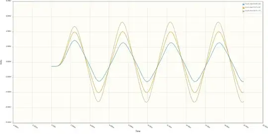
as already mentioned in comments, I did some simulations based on the inductance of the tether, and the inductance of the motor : neither is causing voltage spikes (the damping factor is >=5, so we are strongly over-damped and don't risk oscillations causing spikes)

