0
  • DC 5 V for input

  • Three 10 nF capacitors

  • One 2.2k resistor

  • One 680k resistor

  • Two 5.6k resistors

My assignment is to make an oscillator using only the elements given above.

This is the desired output waveform.

enter image description here

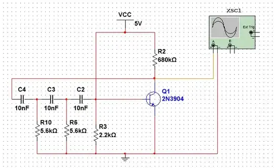
This is the circuit I have tried so far. Please tell me what is wrong and how can I make a circuit with such a waveform.
Null
  • 7,448
  • 17
  • 36
  • 48
Yooseong
  • 3
  • 1
  • 2
    Q1 is not properly biased. And have a look at [this question](https://electronics.stackexchange.com/questions/636341/why-doesnt-the-bypass-capacitor-cause-phase-shift-in-this-oscillator-circuit/636347), it might help. – Rohat Kılıç Sep 28 '22 at 11:42

1 Answers1

2

Please tell me what is wrong and how can I make a circuit with such a waveform.
In your diagram you had base connected to +5 volts and that would have destroyed the BJT.

However, given the component choices you are presented with, this circuit seems to be the most likely one to work. It uses the 680 kΩ to self bias the BJT and will simultaneously present a low-ish impedance to C2 to create enough phase shift to cause oscillation: -

enter image description here

Yup, looks like it'll work: -

enter image description here enter image description here

It oscillates at a shade under 1 kHz.

Andy aka
  • 434,556
  • 28
  • 351
  • 777
  • I'm Korean, so I'm not very good at expressing my gratitude, I really want to thank you for your help. Have a nice day :) – Yooseong Sep 28 '22 at 13:16