1

I am designing Ethernet electronics with an ENC28J60 Ethernet controller for a Raspberry Pi Compute Module 3.

What is the correct way to place the components on the PCB to get the best performance from the chip?

I was searching info and examples, but I don't understand much and the different sources contradict each other. Some examples place the PHY near the Ethernet and others farther away.

I followed the tips from Learn Ethernet PCB Routing.

This is my schematic; I followed the ENC28J60 datasheet:

Ethernet Schematic

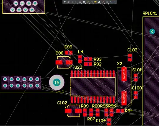
This is my placing, it is correct?

PCB Ethernet placing

Voltage Spike
  • 75,799
  • 36
  • 80
  • 208
  • Is connector location fixed by mechanical constraints, or open to change? Even if not, I see considerable length that can be taken out of the ratsnests. Just about everything is on the wrong side relative to its connections... – Tim Williams Sep 21 '22 at 16:57
  • why have you chosen the ENC28J60 ethernet controller? – jsotola Sep 21 '22 at 17:46
  • @TimWilliams I have a pin connector for ENC28J60 module from old versions. My supervisor told me if this don't disturb to routing don't remove it. Then, to place PHY at least 25 mm from magnetics I put it there. Yes, I am I am seeing some errors in the placement, thanks. I'll change it. – ElectronicGlitch Sep 21 '22 at 18:00
  • @jsotola Because we have a lot of and it's cheap. I don't need too much throughput, mostly only for data. – ElectronicGlitch Sep 21 '22 at 18:02
  • I've never heard of a minimum distance before, and the integrated-magnetics connector is shielded so the PHY can't possibly know the difference (assuming its shell is tied to ground plane). Correction, have heard of it exactly once: https://electronics.stackexchange.com/questions/256333/ethernet-distance-from-phy-to-magnetics which comes entirely without explanation so I'm inclined to disregard it. – Tim Williams Sep 21 '22 at 18:23
  • @TimWilliams maybe, the recommendation of put PHY at least 25 mm from magnetics is when magnetics are outside ethernet. – ElectronicGlitch Sep 22 '22 at 12:51

1 Answers1

3

What is the correct way to place the components on the PCB to get the best performance from the chip?

With 10BASE-T? Not much, route a diff pair with 100 Ω (each trace needing single ended impedance of 50 Ω). Keep the ethernet TX/RX pairs short. Use a continuous ground plane beneath all diff pairs and underneath the Ethernet to SPI converter. You don't have to place the Phy close to the magnetics, but you'll get better results.

It's really when you do 100BASE-T or 1000BASE-T when you have to worry about length matching of the diff pairs.

Also keep bypass capacitors close to the PHY chip.

winny
  • 13,064
  • 6
  • 46
  • 63
Voltage Spike
  • 75,799
  • 36
  • 80
  • 208