If it's a 3-pin connector, it will almost certainly be using the tachometer pin to sense that the fan is present and working. Simply detecting the current through the fan is not reliable, as a fan might stall and draw significant current even though it isn't spinning.
The tachometer signal is generated using a hall-effect sensor inside the fan. As the fan spins, the magnetic field passing the sensor causes a pulse. In the case of a PC, the standard interface works by having the hall-effect sensor effectively short the sense pin to ground each time the fan completes a revolution, with the motherboard pulling the sense pin up to 12V using a resistor. For example:
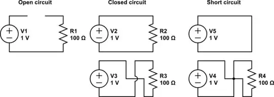
simulate this circuit – Schematic created using CircuitLab
To trick the motherboard into thinking the fan is spinning, you would need to fake the hall sensor pulses, e.g. by having a microcontroller or square wave oscillator drive the gate of a MOSFET placed between the SENSE and GND pins.
Here's an example implementation with a 555 timer.
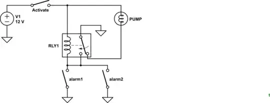
It simulates a fan speed of around 800rpm. You'll need an small N-channel FET with a Vgs(max) and Vds(max) of >12V.
