Aren't B and D the same point and shouldn't it actually be (B and B)?
From a voltage point of view, you are right.
I deal with the node naming issue the following way. Voltage nodes are labeled with a lowercase letter. Current nodes always have an associated voltage. A voltage node may have one or more current nodes. So I name current nodes as a numerical subscript to a voltage node. This allows all current nodes within the same voltage node to have the same letter designation indicating the voltage while having a unique label. So your nodes B and D become b1 and b2 respectively.
For branches I use the label for current as the label from the branch since the definition of a branch is a cascade of elements in series and so all have the same current called the branch current.
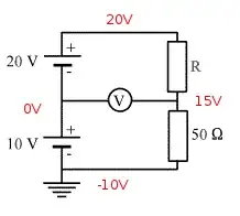
The other answers have calculated the currents, so I won't do it again. What I want to discuss is the equivalences and differences between the two configurations, shown below. So I hope the labeling I have chosen will help clarify.
The two configurations are not the same but they are equivalent for the for the following reasons.
- The load seen by the voltage source is the same.
- The voltages and currents across and through all the resistors are the same.
- The node voltages measured to an arbitrary reference are all the same.
Making these measurements cannot identify the configuration.
Example: The labeling used allows \$V_{bc}\$ to mean the same in both configurations.
What is different between the two configurations is the current nodes within voltage node \$b\$. For clarity the current nodes in the first configuration are labeled \$b_{1}\$ and \$b_{2}\$, while in the second configuration they are labeled \$b_{3}\$ and \$b_{4}\$. They are not the same nodes as KCL will identify.
Measuring the current flows in and out of the node within node \$b\$ will identify the configuration.
So what happened to \$b_{1}\$ and \$b_{2}\$ in the second configuration?
Nothing happened. They just don't exist there. I don't agree that there is some sort of drifting electrons across the diameter of the conductor. Testing with magnetometer should be able to answer this question.
simulate this circuit – Schematic created using CircuitLab
simulate this circuit
Another question is why should there be any current through the 3ohm resistance at all ? Isn't the wire a short circuit and shouldn't current flow through the short circuit across the the 2ohm as it offers less resistance? What is actually going on?
Two things you can always count on:
- Current leaving one end of a component must enter the other end of the component.
- Charge always flows in a closed path regardless whether it is easy or tortuous.
Really these two are different takes on conservation of charge.
It is always a good endeavor to identify the path(s) the charge flow takes to return to its source. It will change direction, divide or split at various nodes.
I hope my notation will help in understanding currents within a network of components.

