3

I want to implement a PT100 sensor measuring circuit using a Wheatstone bridge. Below is a link to the implementation that I suggested. https://www.instructables.com/Measuring-Temperature-Using-a-PT100-and-an-Arduino/

The gain of my differential amplifier LM358P is 10. I noticed that when I have a voltage of 1 mV on the bridge, the output of the amplifier does not get 10 mV but 30 mV. Only above about 20 mV of bridge voltage the amplifier show the correct output voltage. Why is this happening? How to solve this problem?

I also read in the datasheet of the LM358P that the minimal input voltage is 30 mV. I measured the voltage at the amplifier inputs against ground and it is about 100 mV, so this criterion is met.

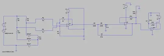
Wheatsone bridge with differential amplifier and Butterworth second order low pass filter

ocrdu
  • 8,705
  • 21
  • 30
  • 42
grandzello
  • 61
  • 3
  • 1
    To measure with a PT100, you should use a 3-wire or 4-wire connection, to reduce errors from the resistance of connection wires. Plenty info on google / wikipedia. A wheatstone bridge uses a variable R2 to balance the PT100, and the output should be a zero voltage indicator, not a linear measurement. With a fixed R2, the output subtracts a fixed voltage, for more accuracy, but then it is not a wheatstone bridge. The current through the PT100 should be 1 mA max, in order to avoid self heating, so better double R3 (and R1). Are you sure you measured that 1 mV accurately? You have a 500 euro DMM? – Roland Sep 09 '22 at 11:36
  • What is your "goal"? Temperature (from ?? to ??). Power supply..ies)? Rail to rail op-amp? Or imposed op-amp LF358? – Antonio51 Sep 09 '22 at 11:52

3 Answers3

4

Depending on the load conditions, the LM358 (like any op-amp, but this one has some quirks) cannot reach the negative supply rail at the output.

enter image description here

Typically it might be able to get to 5mV but only 20mV is guaranteed, and that's with a resistor to the negative rail and no current to be sunk.

Without a resistor, and sinking only 50uA, only 150mV is guaranteed. If it has to sink 1mA, 1V is guaranteed.

So it is better to bias the output over 1V or 150mV depending on what it is driving. Or provide a negative supply rail of -1V or more (negative), but often that's inconvenient both because the supply itself needs to be created and because something like an MCU won't like the input going too negative, and that can cause other problems.

Aside from that, there's typically a mV or so of input offset voltage (can be as much as 4mV), which can be positive or negative, and if it happens to be in the wrong direction it can eat into your bias (and will always show up as an input-referred error equal to the offset voltage).

Spehro Pefhany
  • 376,485
  • 21
  • 320
  • 842
  • Thank you for response! I also added circuit to the post. What do you think about that circuit? It will work? At the output of the differential amplifier there is a second order Buterworth filter with an attenuation frequency of approx. 5 Hz. After the filter there is also a non-inverting amplifier to finally give the output gain of 4. If balanced bridge gives 0V output, how can I bias the output to 1V or 150mV? How to physically implement it? – grandzello Sep 09 '22 at 14:29
3

Your problem seems to be related to the Offset voltage - see Onsemi’s LM358 datasheet, that I highlighted in blue rectangles the Offset voltage (top) and Common mode input voltage range (bottom).
enter image description here

As you seen in Green, the LM358 can go to Zero volt. But management of the Offset voltage needs more attention, as it can be as high as 7~9mV,in Yellow, with nominal values around 2mV. Multiplying by your Gain = 10, we have an offset from 20mV to 70~90mV. The offset on the output values you found are aligned with this.

It means that, even if you have a well-balanced Wheatstone bridge, measuring at 0°C (unbalance = 0mV), you would have the offset error as described above. You have “50%” chance that your offset goes to the positive side, where the output will be positive.
The other “50%” is worse, as the output would try to go below 0 Volt, but your single-rail power supply does not offer that and you will have a non-linear response for signals of small amplitude, near zero, due to “negative offset”.

Another post here discusses possible ways to implement offset-null adjustments for an Op-Amp that does not have offset adjustment pins.


Supplement - Offset adjustment
Repositioning the voltage output &
Fine-balancing the Wheatstone bridge:

As another answer informed, the Output voltage of the LM358 may not be able to swing near GND rail, depending of the load impedance.
Uses of the Offset adjustment: Offset adj. could set the “zero” temperature to zero output (original answer), but also could correct small unbalances in the Wheatstone bridge - I forgot to mention that.
Furthermore, an “oversized” offset adj. could be used to compensate not just 10mV, but up to 50~100mV of offset; this would result in higher output voltage swing, where 500mV~1V would then signify “zero” Temperature.
Minimum voltage, Zero °C and Sensor check: The intentional offset of zero signal could be helpful to verify if instrumentation is working properly, like famous industrial instruments using 1-5V or 4-20mA for remote transducers.
For instance, If your “Arduino” or CPU sees less than “1V”, there is a broken wire or another problem. Obviously you will loose some excursion range (e.g. 0-5V now being 1-5V) in terms of the digital conversion & resolution, where I think loosing less than 1 bit but gaining a higher confidence (things running OK and properly connected) is more than worth the extra effort.
EJE
  • 1,412
  • 4
  • 22
-2

Opamps are not linear in all of their range, they are made of transistors (BJT or MOSFET doesn't really matter=) which are generally non linear components but have a range of voltages where they are linear.

Miss Mulan
  • 1
  • 1
  • 5
  • 11