2

I finally made an improved choke from a MOT. It used 12 gauge insulated wire and measured 3mH on my LCR meter. It has a 1mm air gap made with a sheet of acrylic sandwiched between the E and I and epoxied together.

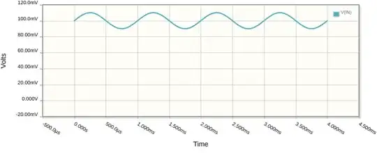
The noise problem was remedied in this new design, but heat seems to be my next hurdle. The wire became so hot that the insulation melted together between coils allowing the copper to touch. Up to this point the system was running smoothly and allowed me to take the scope waveform below:

enter image description here

As a refresher, I am attempting to convert a kiln to DC power. It is controlled using an SCR and outputs the AC power to a full wave bridge rectifier. The rectified AC was run through the choke and into a set of 200V, 10,000uF capacitors run in series.

I am especially interested to know if this waveform looks like a good endpoint or if my choke is saturated or needs some other tweak. I think I can find a high temperature insulated wire and possiblyuse a heat sink/fan for a new choke coil but I'd really like to know if I'm as close to DC as possible.

Here is a picture of the choke coil after the melted coil wire was removed. The air gap is a piece of 0.04" acrylic https://www.amazon.com/dp/B099DHKJPM?psc=1&ref=ppx_yo2ov_dt_b_product_details This version was near silent even when ramping up to over 200V. The resistance of the heater elements is 22.2 ohms based on 240V and 2600W specs by the manufacturer. choke coil measured
  • 2
    It's hard to see just what you are showing there. It might be about 1 volt peak-to-peak over a 6 mSec portion of the DC waveform on the capacitor going to the heater, and if that's about 100 VDC, it's about as good as you're going to get. You should also show a simultaneous trace of the waveform from the SCRs. And how much current was flowing? #12 AWG magnet wire should be able to handle about 30 amps. But it'd be a good idea to embed a thermistor or thermal switch to detect overheating. – PStechPaul Sep 07 '22 at 02:22
  • 1
    According to this chart https://www.powerstream.com/Wire_Size.htm #12 AWG wire is good for 41 amps when used for chassis wiring, but only 9.5 amps for power transmission. The following chart shows 13.5 amps for transformer winding. https://www.electrical4u.net/transformer/swg-to-current-amperage-chart-transformer-wire-amperage-table/ – PStechPaul Sep 07 '22 at 02:39
  • 2
    You are making it hard for yourself. You could visit your local junkyard/metal recyclers and look for old 3 phase motors (remove the rotor) , reactors for power factor or old variable speed drives. You should be able to source plenty of inductance for next to nix. Or talk to your local motor rewinder and hopefully they might be able to guide you to a cheap solution. – Kartman Sep 07 '22 at 02:49
  • @PSTechPaul The magnet wire was a total bust. The coating is so thin that it's just not feasible to wind it across a metal edge without scraping off the insulation. I tried taping over the edges and even applied varnish but after 50 or more winds, stuff happens. I appreciate the diagnosis of the trace as "good as it gets". That gives me enough confidence to go ahead and do it again with high temp insulated wire. I'll probably add some sort of heat sink also to keep the core from getting so hot. – Daniel Van Antwerp Sep 07 '22 at 04:05
  • You still need to verify my guesses about what you were measuring. Also, see my simulation below and understand that for 8 amps into the heater load, the inductor carries 17 amps. But I have no idea what values you are actually seeing. Until then, I'm just guessing, and maybe the ripple was more like the 20 volts I observed in simulation. Also, you should use a bobbin. – PStechPaul Sep 07 '22 at 04:34
  • @PStechPaul My probe was on the positive going into the heater load. I wish I had thought of connecting a second one to simultaneously compare the waveforms. It will take some time to get the new choke built but I will report back with current measurements. I tried a cardboard bobbin with the magnet wire but the corners are just too sharp and eventually it wore through. In order to get a tight winding, a decent amount of force is required and it's just hard on the wire. I worry the high temp stuff is going to be tough to pack and limit my turns. Tough project! – Daniel Van Antwerp Sep 07 '22 at 16:40
  • Please take some photos of your (re)build at various points to show details of items such as adding the gaps and making the bobbin. It might be better to use multiple windings made from smaller gauge wire, in parallel. #12 AWG is equivalent to three #15 AWG or six #18 AWG. – PStechPaul Sep 07 '22 at 20:43
  • @PSTechPaul By multiple windings, are you suggesting more than 1 choke? I'm hopeful that by optimizing insulation and cooling that #12 AWG works. The test conditions are a little tricky. I'm keeping the furnace at 2100F which requires a pretty consistent 75V. When I wire in the choke, I turn everything off so the furnace drops down (~1850F) . I turn it back on and it needs to catch up. It hits max voltage and then pulls back as the controller ramps at 200F/hr. It can't really stabilize until it reaches the setpoint. Maybe I should make the "test" setpoint whatever the temp is after wiring. – Daniel Van Antwerp Sep 08 '22 at 00:17
  • It's going to be really hard to get a decent winding with the laminations glued together like that. And that prevents you from properly using a bobbin. Also, acrylic may not be the best material for the gap, as it melts at 220-250C, and its mold temperature is 50-180C, at which point it may weaken and deform. https://plasticranger.com/melting-point-of-plastics/ Chokes usually use something like Bakelite or Fiberglass - a PC board might work, although most are 1/16" (1.5 mm). It would be useful to try a couple thicknesses before final gluing. – PStechPaul Sep 08 '22 at 01:09
  • Let us [continue this discussion in chat](https://chat.stackexchange.com/rooms/139058/discussion-between-daniel-van-antwerp-and-pstechpaul). – Daniel Van Antwerp Sep 08 '22 at 01:16
  • What does MOT mean? I found [a lot of meanings](https://www.allacronyms.com/MOT/technology). I guess it's *Microwave Oven Transformer*, but since it's not a so common acronym it's good practice to state it in your post. – LorenzoDonati4Ukraine-OnStrike Sep 08 '22 at 19:53
  • @LorenzoDonatisupportUkraine That's correct! I should identify the meaning of the acronym before using it which I think I did at some point. Such a pain to spell it all out. I'm always having to use the urban dictionaries to understand a new acronym to understand the context of some news or social media post. Very annoying...IMHO :) – Daniel Van Antwerp Sep 08 '22 at 20:01

1 Answers1

1

I ran a simulation using a 3 mH choke and a 10 uF capacitor, into a 30 ohm load, at 50% (90 degrees) firing angle. This results in an output of about 250 VDC and 8.38 amps, with about 20V P-P ripple. But the inductor current is 17 amps RMS.

SCR DC output simulation

This answer provides some clue as to the reason why the OP experienced such major overheating, which is higher RMS current than what was originally expected. But I cannot give a more definitive answer until he provides more of the information requested. Specifically:

  1. Resistance of the load (heater)
  2. DC voltage on heater (in parallel with capacitors)
  3. AC voltage on heater (peak-to-peak and RMS)
  4. True RMS of voltage into choke (and waveform)
  5. True RMS current through choke (and waveform)
  6. Dimensions of choke laminations
  7. Number of turns
  8. Temperature of windings as function of time
  9. An accurate schematic of the entire circuit (with values)

Some of these measurements might be difficult (and dangerous), given the level of proficiency and experience observed. So the OP should ask before attempting them, especially when working on a 5 kW 220 VAC source. Unless the source is isolated, there are no points that can be connected to GND (and scope). But there are ways to do it safely.

(edit) I had mistakenly used a sine wave period of 10 mSec (100 Hz) in my previous simulation, and after correction I have this for 50% (90 degrees) phase modulation:

SCR DC Output 50% Modulation

Notice that the output is 244 VDC, which is higher than the 218 VDC obtained at 90% modulation:

SCR DC Output 90% Modulation

This may be caused by some resonance effect. 3 mH and 10,000 uF resonates at 29 Hz.

Here is the simulation for 20% (144 deg) modulation, which results in close to @DanielVanAntwerp's 75V nominal sustained voltage.

SCR DC Output 20% Modulation

So the problem with choke overheating may have been caused by applying full AC voltage to the L-C circuit, where about 29 amps was flowing through the windings. Setting the PWM control to 50% or a bit less should result in effectively full power to the heater with less than 20 amps which is half the power of 30 amps.

Note: I used 50 mOhms for the choke's resistance, and 500 mOhms for the capacitor's ESR.

(edit 2) I tried using a 3370 uF capacitor which resonates with 3 mH at 50 Hz, and there are 500 amp surges in the choke. So it is important to make sure the capacitor and choke are chosen to avoid resonance, and testing should be done to see the maximum percent modulation before excess current occurs.

PStechPaul
  • 7,195
  • 1
  • 7
  • 23
  • @PSTechPaul I have spent most of the day looking for a good wire to repeat the windings. I found a chart listing the current max for PTFE coated wire and it provides a derating factor for bundling. 12 AWG is 55A which is derated by 0.5 at 30 bundles. If I get 50 wraps (big if) that's maybe a 0.3 derating which comes to 16.5A. PTFE has the same heat resistance as silicone insulation (200C) but it's a smaller overall diameter. I have also ordered a pair of heat sinks for the top and bottom of the choke. https://catalog.connectronicscorp.com/Asset/WIREMAX-conductor-CURRENT--2-.pdf – Daniel Van Antwerp Sep 07 '22 at 23:04
  • After getting more information, and making a correction to my simulation, I found that at 50% (90 deg) phase modulation, the output is about 244 VDC (11A into 22 ohm load), and the choke sees 19.2A RMS. If the windings are 500 mOhms that's about 19 watts. If your steady state is 75 volts, for 20% (144 deg) modulation, output is 79.5 V, 3.58 A, and 7.7 A in the choke (7.7 W). At 90% (18 deg) modulation, output is 218 V, 9.8 A, and 28.7 A into the choke, for 41.6 W. So running at 50% actually results in a higher DC output and less RMS current in the choke! – PStechPaul Sep 08 '22 at 02:17
  • I'm trying to derive your wattage numbers which don't seem as simple as P=i^2R. For your 50% sim, I get P= (19.2A)^2 * 0.5 ohms = 184 W. In any event, my PID controller has the ability to maximize the output allowed by the SCR. Would you suggest I set this at 50% knowing that it will have sufficient power AND remain within the safe working current range of a choke with 12AWG PTFE windings? – Daniel Van Antwerp Sep 08 '22 at 18:29
  • I actually used 50 mOhms for the choke winding resistance. I'll edit my answer to include this information. Of course, I don't know your actual winding resistance, and it will increase with temperature. – PStechPaul Sep 08 '22 at 19:10
  • You will need to provide more details and actual measured values and waveforms for your components. See if you can take measurements at various phase angles, from 10% to 60% or so. – PStechPaul Sep 08 '22 at 19:18
  • #12 AWG wire has 0.0015 ohms/ft. I estimate that 30 turns wth an average diameter of 75 mm is about 23 ft, for about 35 mOhms resistance. – PStechPaul Sep 08 '22 at 19:31
  • @DanielVanAntwerp If the wire is likely to be heated to 250 °C or more you may want to avoid PTFE because at that temperature it starts to give off toxic gases: [Wikipedia:PTFE](https://en.wikipedia.org/wiki/Polytetrafluoroethylene#Safety). Bear in mind that the inner windings may be substantially hotter than the outer layers. – Andrew Morton Sep 08 '22 at 19:32
  • Thanks for the clarification @PStechPaul. I can tell you that I used up nearly every bit of a 100ft spool of 12 awg in the making of the 3mH choke that failed (`150m Ohms?). I have a 100 feet of PTFE insulated 12 awg on the way. @Andrew Morton your point is well taken. While some glassblowers even use teflon tools, that is a step too far for me. However, I do have ample ventilation in my shop and won't worry about the vapors. Hopefully it never gets that hot! There are lots of possible hazards but our biggest concern is particulate in the form of silica dust. – Daniel Van Antwerp Sep 08 '22 at 19:50