6

How do I calculate the time it takes for the current to decay in an inductor when a freewheeling diode is used?

I've tried using just L/R but the result is never right when I simulate in LTSpice

Then I tried calculating the total energy in the inductor when the switch is turned off, and calculating the power loss across the diode, assuming constant voltage drop and current, and it gives better results but still not accurate.

I at least get an order of magnitude accuracy and in the right direction when swapping diodes with different voltage drops e.g. normal to schottkey.

I was neglecting R, but in my simulation this is only 1mOhm

So how do I do it?

Inductor and freewheeling diode

AQUAMAN
  • 361
  • 1
  • 7
  • 3
    _"I've tried using just L/R but the result is never right when I simulate in LTSpice"_ - please provide an example of your calculation vs LTSpice. – Bruce Abbott Aug 29 '22 at 21:48
  • You can set the series resistance of the inductor in LTSpice. You can run a transient analysis showing a graph of inductor current and voltage vs time, then take a screenshot and post it in your question. – PStechPaul Aug 30 '22 at 04:41
  • This is a difficult problem, since it could involve parasitic capacitances and other effects. See this [old answer of mine](https://electronics.stackexchange.com/a/171986/29434). – LorenzoDonati4Ukraine-OnStrike Aug 30 '22 at 13:09

3 Answers3

5

assuming constant voltage drop and current

The inductor current is a ramp, not constant. Also, unless the inductor currents are close to the rated current of the diode, the diode voltage drop will be nowhere near any idealized value. E.g. if the diode is silicon, as I've simulated below, the diode drop is not 0.7V!

I've tried using just L/R but the result is never right when I simulate in LTSpice

The R you're speaking of would be the equivalent resistance of the diode - you'd be replacing the diode with a resistor, and would have to set the resistance to approximate the diode's behavior. This is not impossible, but choosing the correct value of R would require... a simulation first. The R is specific to your circuit and waveform, and not a property of the diode itself. But all this crude modeling is unnecessary anyway.


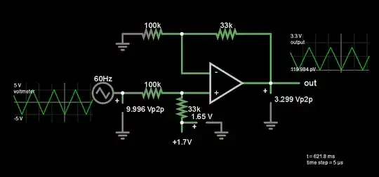
Let's set up a simulation here in CircuitLab: PWM frequency 20kHz, PWM control voltage range 0-10V, PWM output voltage 0-5V. So, the PWM pulses are 1% of 50us, so 500ns wide. The voltage-controlled voltage source is just a x4 amplifier, so VPWM is a train of 20V, 500ns rectangular pulses.

schematic

simulate this circuit – Schematic created using CircuitLab

The inductor current waveform for each PWM pulse:

Inductor current waveform

The D1 diode voltage during each PWM cycle:

Diode voltage waveform

The average diode voltage drop is about 0.4V, not 0.7V!

The inductor current at the end of the pulse is $$ I = \frac{1}{L} \int V dt = (10{\,\rm \mu H})^-1 \cdot 20{\,\rm V} \cdot 500{\,\rm ns} = 1{\,\rm A}. $$ This agrees with the simulation.

The rate of change of current in the inductor is determined by the inductor voltage, set by the diode voltage across D1. We consider the inductor "discharged" when the current falls back to 0: $$ \Delta I = \frac{1}{L} \int V dt = \frac{1}{L} \cdot V \cdot T \\ T = \Delta I \frac{L}{V} = -1{\,\rm A} \frac{10{\,\rm \mu H}}{-0.4{\,\rm V}} = 25{\,\rm\mu s}. $$

This matches the inductor discharge time in the simulation.

4

Maybe if you need a fairly short flux reset time AND you have plenty of overload volts to spare in your choice of MOSFET, you can add a fixed value resistor in series with the diode. For instance, if your inductor was taking 1 amp when the MOSFET opens, adding a 10 Ω resistor will cause a back emf not of 0.7 volts (-ish) but 10.7 volts. So, if your power supply is (say) 24 volts, the peak drain voltage would be 34.7 volts and quite possibly easily handled by the MOSFET.

This then allows you to use the resistance of the resistor as the dominant component in more accurately calculating the time it takes for the magnetic energy stored (or current) in the inductor to fall to (say) 1%.

Of course, if you didn't take into account the DC resistance of the inductor it might have caused a significant error in your original calculations.

Andy aka
  • 434,556
  • 28
  • 351
  • 777
0

You could try v = L.di/dt and so dt = L.di/v where di = the current in the inductor at DUT switch off and v = 0.7 V.

I'd be interested in the result.