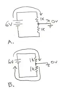
Other answers did a thorough job explaining the need for a current to flow in a circuit: a loop. Car racing circuit = car racing loop, as a mnemonic aid. “Circuit” and “loop” are synonyms(-ish).
But the circuit you’ve drawn is also a building block in electronic circuits. There are many uses of it. One is when we need supply voltages that go “around” some signal, ie. are always above and below it, with a fixed voltage (“distance”) from the signal. This is often found in linear bench power supply designs, for example.
Imagine that the “ground” you’ve drawn is the output (+) terminal of a power supply with a range from 0 to 150V. Obviously most ICs like op-amps and small signal transistors won’t survive being powered from 150V. But we can get the +/- 12V supply floating around the output (+) terminal. Instead of batteries, one uses the secondary winding of a mains transformer, an a rectifier.
Another way to “add a floating voltage” in a circuit is with current sources. If there is a resistor somewhere in the circuit, one can connect a current source around it. The current shunted through the resistor will generate a voltage per Ohm’s law, as-if a battery was added in series. This takes a differential output current source (aka a floating current source), and finds some applications in analog circuits, but not only.
Suppose we have a low impedance digital output and want to shift the levels up or down by a fixed offset voltage. Add a series resistor to the output, and have a current source drive current into/out of the resistor. The resistor can be AC bypassed with a capacitor. The “free” end of the resistor will have the logic signal offset by an offset voltage that’s the product of resistance and current (Ohm’s law).

