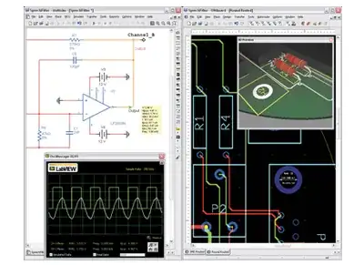
In the leftmost schematic shown below, the OP's original circuit is reproduced, with some resistances added. Each battery has an internal resistance. The motor has an internal resistance as well (Rmotor).

simulate this circuit – Schematic created using CircuitLab
Can we measure all these resistances?
Not easily.
The motor's resistance (Rmotor) is quite low. For a brushed DC motor, its resistance is measured in series with its two brushes. Brush resistance is variable, and for some angles-of-rotation shorts or connects internal windings in parallel. If you try to measure Rmotor resistance with an ohmmeter, you'll likely find that it jumps around - the lowest resistance you see is likely somewhat closer to the truth. Another problem with a different Rmotor measurement method is outlined below.
What about battery resistance?
Batteries tend to be non-linear devices, where internal resistance can vary with state-of-discharge. And short-circuit resistance likely differs from this scenario, where less current flows.
The technique of properly measuring battery resistance is a bit awkward. A resistor of known value is placed across the battery. Open-circuit battery voltage \$V_{UNLOADED}\$ is compared with the smaller voltage \$V_{LOADED}\$ measured while the resistor \$R_{load}\$ is attached:
\$ RB1=({V_{UNLOADED}\over{V_{LOADED}}}-1)R_{load}\$
In the second circuit on right, you can combine all the battery resistances into one (3xRB1) since they're all in series.
The model for the motor has been made more complex by adding a voltage source in series with it's static resistance Rmotor. When the motor turns, it generates a voltage (\$V_{bemf}\$) that tends to reduce current flowing from V1. A DC ammeter could measure this current.
We could use this measured current to find RB1...
\$3\times RB1=(V_{UNLOADED}-V_{LOADED}) I_{MEASURED}\$
While the motor is turning, \$V_{bemf}\$ cannot be measured, since it is inside the motor, and is rotating. It will be less than the 12V applied, because of brush losses. So motor resistance Rmotor cannot be determined by simply knowing the current flowing through it.
One could try to grab the motor shaft to stall it (on a weak toy motor) so that \$V_{bemf}\$ falls to zero. Then Rmotor would be simply \$12V\over{I_{MEASURED}}\$. However, since current will be very high, you will no longer have 12V applied...it will have dropped lower due to 3xRB1. So you would need two meters, one to measure current, and one to measure voltage at the motor's terminals.
You would also find that a stalled-motor will give a current that jumps around quite a bit because of brush resistance - same problem as the ohmmeter method.


