3

I don't have problems working with low voltages like 12V, but when I started working with higher voltages using MOSFETs, I ran into problems with MOSFETs overheating. I tried anything that came to mind but with no success.

I am using old components, transistors, resistors, MOSFETs, etc. I picked them up from old electronic devices I have, but I always check them before using them.

So I have some questions and I would appreciate any help.

My questions are:

Can MOSFETs handle high voltages, like 100 V and 220 V DC? I researched that, but I got confused, because some websites say that they can handle way more than 220 V, and some say they can't, or that you can't use MOSFETs like that.

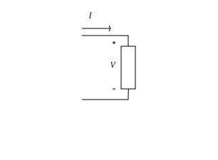
Also, if a MOSFET can handle 100 V and 220 V, can we use it as a simple switch in a simple circuit with 220 V, like in this picture below?

schematic

simulate this circuit – Schematic created using CircuitLab

When I tried to use it as a simple switch with 220 V it got very hot quickly, and even when I used it with 20 V it got hot. What is the problem, am I using it wrong?

Also, most of the MOSFETs I have seem to pass current from the gate to both the source and the drain. I checked the datasheets and I found out that they were enhancement n-channel MOSFETs, so I am very confused.

  • 2
    Please specify the MOSFET part number. Learn to read the datasheets. The gate to source voltage controls the drain to source switch. The top circuit won't work well at all because the gate voltage isn't relative to the source. On the bottom circuit, the gate voltage is way too high, you probably damaged the MOSFET. – Mattman944 Aug 25 '22 at 01:16
  • Not every MOSFET is designed for every use, and high voltage means a signal might carry a small (by percentage) AC or DC component of what it primarily is not, but be enough to throw off your component selection. Switching high voltage DC on and off can be quite precarious. – Abel Aug 25 '22 at 01:52
  • what i am working with now it seems a transistors, E13007, E13009, but i had several of them that i am sure are mosfets, –  Aug 25 '22 at 02:07
  • i cant remember its part number, i damaged them of trying again and again to solve this problem, but i can remember the part number of two of them is IRF400 or IRF460, i cant remember exactely, but i am sure is IRF4??, and i got the same problem of overheat, also about the two exemple in the picture, i tried both exemple, but now i appreciate your advice about the circuit in top of the picture being wrong, i tried a lots of ways, i am having this problem for a while, it makes me tired. –  Aug 25 '22 at 02:07
  • 1
    You should really learn how to use a simulator like LTSpice, instead of burning up transistors and maybe hurting yourself. You should also have some idea of what you are trying to do, such as turning on a 120V lamp using a 12V signal. – PStechPaul Aug 25 '22 at 03:04
  • Please edit the question to limit it to a specific problem with enough detail to identify an adequate answer. – Community Aug 25 '22 at 04:37
  • okey, my qustion is : does power mosfets can be used as a simple switch like in my picture with voltage as 100 or 220 volt? –  Aug 25 '22 at 06:26
  • 2
    Some can, some can't. As others have been trying to say it depends entirely on the part in question. There's literally thousands of different MOSFET types out there with wildly varying specs. – Unimportant Aug 25 '22 at 08:39
  • thanks, This is what I wanted to know, –  Aug 25 '22 at 09:23
  • 1
    If you want to use a FET with a high voltage supply then you’ll need a device that’s rated for that voltage (obviously) and you’ll need to be able to switch it quickly if you want to avoid excessive heating. This calls for an appropriate gate voltage (check the datasheet for the device) and a reasonably fast rise/fall time. Also be aware that high voltage devices tend to have a higher RDSon than lower voltage parts. – Frog Aug 25 '22 at 10:12
  • i have made an oscillator circuit to control the mosfet, to make it switch quickly, but with no change, the overheating remained, and the most confusing, i have this problem even with 20, 30v, i have a transformer 220v/25v so i puted a diode in the circuit which include a light bulb of 20v and the mosfet just to test it on half circle and yet it the mosfet got hot, and i convert it to DC i got 30v or 30 something, i tested it this time with an electromagnetic coil that works with 30v or more, but also got hot. –  Aug 25 '22 at 13:36
  • 1
    The first circuit will definitely overhead. The second one, not sure, it depends on the gate voltage and the specific kind of MOSFET. – user253751 Aug 25 '22 at 14:40
  • i will buy some of IRF634 8.1A 250V N-Channel Power MOSFET, IRF644 14A 250V N-Channel Power MOSFET, IRF740 10A 400V N-Channel Power MOSFET, IRF840 8A 500V N-Channel Power MOSFET, and i will tested them, thank you for reply. –  Aug 25 '22 at 16:11
  • 1
    250V rating is not enough for rectified 220V mains, since rectified mains is about 300V! The lowest you want to go is 400V. 500V is even better. – Kuba hasn't forgotten Monica Aug 26 '22 at 01:52
  • MOSFET are controlled by the voltage DIFFERENCE between their gate and source terminals. They are NOT controlled by the voltage you apply to the gate relative to ground, where ground might be virtually anywhere else in the circuit. If you apply a voltage referenced to GND to the gate and the source terminal is not connected to GND, the MOSFET doesn't care or know. It can't know. The MOSFET can only see voltage differences between its terminals. – DKNguyen Aug 26 '22 at 03:13
  • From the question it sounds like you're using salvaged random MOSFETs, and connecting them to mains. That's a very bad idea. Different parts have wildly different ratings and will be suitable for different purposes. Decide what you want to do, and choose a MOSFET with known parameters appropriately. Also, please don't mess with mains if you don't know what you're doing, it's too easy to start a fire or electrocute yourself. – marcelm Aug 26 '22 at 13:20

1 Answers1

3

The circuit on the left won't work, and as soon as you connect it to power, the mosfet will be destroyed. Those mosfets that conduct from gate to drain/source have been damaged that way.

Mosfets have some maximum gate-source voltage, and the circuit on the left, with lamp connected from source to ground, will bring the gate down to almost -220V as soon as the mosfet turns on, destroying the gate.

There is only a very thin oxide layer between the gate and the channel. DO NOT consider gate to be isolated or safe to touch!

Can MOSFETs handle high voltages, like 100 V and 220 V DC?

MOSFETs in general? Yes. Any MOSFETs in particular? No. Not unless you read its datasheet and confirm what it can handle. Every MOSFET has a part number. You'll have to learn to recognize which part of the text printed on the case is the part number, and how to find and understand the MOSFET datasheets. There are some online resources for that.

If I were to play with an NMOS as a light-bulb switcher, I would do it as follows:

schematic

simulate this circuit – Schematic created using CircuitLab

The M1 part number is just a suggestion. There are other parts just as suited. The button should be rated for 220VAC at least, even though it's switching 9V. All connections must be insulated, even on the gate side. Keep it in a tight plastic enclosure. D1 isolate the battery if the mosfet's gate got damaged, and prevents it from exploding in that case. R1 acts as a fusible resistor and should be a ideally a flameproof resistor.

D2-D9 form a full bridge, rectifying 220V AC. The circuit works as shown, but you must understand that just because it works, doesn't make it safe to play with.

There's no need to rectify the mains voltage, though: you can use two MOSFETs back-to-back:

schematic

simulate this circuit

Do not play with this without an isolation transformer. If you can't find an isolation transformer (with 220VAC input and output), you can make one from two identical 12V, 24V or 48V secondary voltage transformers connected back-to-back, rated for lamp's wattage:

schematic

simulate this circuit

  • i understood your answer, and i appreciate your time and help, but about this isolation transformer in the circuit, Does its purpose in this circuit is only for protection? like electric shock?, which mean that the circuit can work without it?, or it has some role in this circuit like prevent the bridge rectifier from overheat? because i faced this problem too? thank you. –  Aug 29 '22 at 17:17
  • The purpose is indeed for electric shock protection. Otherwise, anyone trying to replace the 9V battery would be exposed to mains voltages, and SW1 would need to be a switch rated for line voltage, not for 9V - to protect the user who'd press down on the button. – Kuba hasn't forgotten Monica Feb 14 '23 at 01:48
  • An alternative approach would use an optoisolator instead of an isolation transformer. – Kuba hasn't forgotten Monica Feb 14 '23 at 01:50