4

Hello i am designing a small Li-ion battery charger based on an custom generator which produces 36v DC output and i have designed a PCB that controls the whole procedure and logs the measured data to an SD card using an esp32. I also have a 4-20mA sensors which reads the fuel level.

I need to measure the following

  1. Voltage of Li-ion ( i believe it is 72v nominal & 82v fully charged ).

1.1 Voltage of the generator (36VDC but it takes some time to fully stabilize).

1.2 Voltage of a lead-acid battery that jump starts the generator(12v nominal, 13,8v fully charged).

  1. 4-20mA level sensor @ 24V
  2. Also i have some digital inputs that are on a different voltage (5v) than ESP32 i would like to read.

1) Voltage Measurement

enter image description here

I used a simple voltage divider to measure each voltage while using a high value R1 in order to minimize the current flowing i also added a small cap to stabilize the output for the ADS1115 ADC All the packages are 0805 except the Li-ion voltage divider that uses a 1210 package for higher thermal and voltage protection.

Does it look correct?

2) 4-20mA Sensor

enter image description here

The schematic has been copied from here and because there is no stock of 50Ohm resistors i opted for 2 100Ohm in parallel at the time i designed the schematic, i will probably change them to a single 50Ohm and solder them by hand.

Question 1. Does anybody know why they use the 100Ohm (R3) to GND ?

I guess that the 3.3kOhm resistors in series are there for over-current protection?

3) Digital Inputs

enter image description here enter image description here

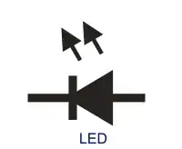
I used the above mentioned opt-transistor and the resistors are chosen based on a voltage input of 5v and a led Vf of 1.2v and If of 20mA with a reasonable margin of the recommended led values

Rled = (Vs - Vf)/If = 190Ohm

While the transistor resistors(1kOhm) are selected as a current limiting device

DC/DC Step-Up && Step-Down Converters

I used https://webench.ti.com/power-designer/ to copy the step-up and down schematics and PCBs and since it is my first time "drawing" using dc/dc i am extremely worried about the emf and the power dissipation that they may produce.

Link of the design

According to the ti designer my biggest power dissipation dc to dc is the 12v to 24v step up with a total power dissipation of 5.8W and i was wondering if i need to add some kind of heat sink in order to improve it.

Here is my layout

enter image description here

I used 4mm holes stitched between planes as a heatsink and i am thinking of adding a small fan to help with the power dissipation would that suffice or do i have to add a heatsink on the diode?

Noise

I am really worried that the noise for the dc/dc converters will affect my contraption so i opted for a sandwich layout, bottom layer of the main PCB is GND.

enter image description here

I will use 10-20mm pin headers to increase the distance of the 2 boards in a 3d printed case and i was wondering if i should predict for some kind of shielding "buried" between the 2 layers or the distance is enough to prevent EMF from the DC/DC Converters

Step-up frequency is at 400khz and step down around 530khz.

I would love for some advice if anyone can confirm that my assumptions are correct or (as usual) wrong.
geocheats2
  • 77
  • 5
  • The current loop reading seems a bit weird. I usually put the ADC input "above" the 150R not in the middle of 50 and 100 as is done here. Then you get 3V at 20 mA. The 3k3 forms a lowpass filter (at almost 500 Hz) with the 100nF. – Dejvid_no1 Aug 21 '22 at 10:59
  • Also place some caps on the ADC supply. – Dejvid_no1 Aug 21 '22 at 11:01
  • @Dejvid_no1 (4-20) i don't get what you saying with the "above" could you make some schematic?. Considering this https://storage.googleapis.com/circuitar-web-media/product/142/files/ADC_4-20_v1.2_EN.pdf should i replace the 50Ohm with a 150Ohm ??? or the 50+100Ohm is the 150Ohm resistor and if yes why do i measure the voltage only on the 100Ohm ?. Also i haven't added any decoupling caps yet, if you mean that. – geocheats2 Aug 21 '22 at 11:16
  • Noise is not the only concern. All those ADC voltage measurements require a common ground. Some of those voltage sources are likely some distance away, and some can carry considerable current. Establishing a good common ground that doesn't introduce offsets may be more difficult than you imagine. – glen_geek Aug 21 '22 at 14:54
  • @geocheats2 I think Spehro anwers all your questions. I only meant that I usually measure over the total 150R, but that might not work with your ADC input range. – Dejvid_no1 Aug 21 '22 at 16:51

1 Answers1

6

There are many questions here- I’ll just address the current loop question. The 100 ohm resistor to ground is where the measurement actually takes place. For accuracy, you should take care that the PCB traces don’t add to the resistance. For example, on the high end have one trace conducting the 20mA and another from the 100 ohm resistor to the 3.3k. It would be better to use differential measurement across the resistor (2 inputs required).

The choice of 100 ohms is to allow a relatively high voltage for the ADS1115 to measure, and still have some headroom (up to 33mA) before exceeding the power supply rail- some 4~20mA transmitters can produce 30mA-ish outputs when then input is out of range.

Assuming the ADS1115 is configured for 2.048 volts FS, then 1LSB is 63uV so 5mm (0.2”) of 8mil 1oz trace will add almost 4 LSB to the reading. Of course that’s only 0.01% so if your requirements are modest it may not matter to you.

The series 50 ohms is not very important- it could be zero or higher than 50 ohms depending on the compliance of the transmitter. 500 ohms 1W 5% might be fine (600 ohms total -> 12V drop at the input for a transmitter powered by 24V).

Higher values provide a certain amount of protection in case the input is accidentally shorted to 24V. As shown, a short to 24V will cook the input resistors and may damage the ADC.

To make it survive a short to +82V without compromising accuracy unduly is quite possible but would require more parts and more effort.

Spehro Pefhany
  • 376,485
  • 21
  • 320
  • 842