3

I have a DC signal from a DAC in the range of [0:3,3]V and want to convert it to be in the range [-5:5]V. My approach would be to scale with op-amp with gain 3 and then DC offset.

I've read that this could be done simultaneously by using an op-amp. By using inverting amplifier with gain 3 but instead of grounding the noninverting terminal apply biasing voltage connected to a voltage divider.

After that I can use an inverting buffer to make the map correct (0 to -5;3.3 to 5.)

Is this how this would be done? Should I apply negative bias voltage to bring the midpoint of my range down? Are there any additional things to consider?

JRE
  • 67,678
  • 8
  • 104
  • 179
  • 1
    I think you have the right idea. Unless you want a fast response to DAC changes or a high current capability then that should be all you need. Choose an op amp with rail-to-rail output capability if you’re using +/-5V supplies. – Frog Aug 16 '22 at 09:10
  • 1
    As far as the biasing goes, start at the mid-point of the DAC range, so for 1.65V from the DAC you want 0V output from the op amp. You’ll want a ratio of 1.65:5.0 so perhaps use 33k from the DAC output to the op amp non-inverting input and from there 100k to the -5V supply. The maximum output from the DAC will be 3.3V so the divider will divide that down to (8.3 * 5.0/6.65) -5.0 =1.24 so you’ll want a gain of 5/1.24 = 4.03, so choose some suitable feedback resistors e.g. 100k from the op amp output to the inverting input and then 25k (give or take) from the inverting input to ground. – Frog Aug 16 '22 at 09:25
  • I’ve skipped a couple of steps in the calculations, can expand on those if you need. – Frog Aug 16 '22 at 09:26
  • @Frog can you elaborate on the formula for the divider? – Ognyan Petkov Aug 16 '22 at 10:50
  • What power supply voltage is available? Presumably this circuit is to be used with the arduino and the circuitry on the input side which I designed for you in your previous question. Have you decided whether to use +9 V or + 12 V on the input side? It makes sense to use the same power rail on the output side as you intend using on the input side and what this power rail voltage is partly determines the design of the circuitry you are now asking for. –  Aug 16 '22 at 11:05
  • Sure. First I’d bias the DAC output so it’s at 0V for mid-range. This means that I can just apply a certain gain to give a +/-5V output. If the mid-scale input to the op amp is to be zero then I’ll need to divide between the DAC output)always positive) and some negative voltage. The -5V rail is an obvious option. I’ve chosen a ratio so that 1.65V from the DAC yields 0V to the op amp, and I can calculate the lowest and highest voltages that will be presented when the DAC outputs 0V and 3.3V, so I know the gain that will be needed to amplify that to +/-5V. – Frog Aug 16 '22 at 11:06
  • I’ve chosen values in the range 10-100k because these won’t significantly load the DAC but aren’t so high that they will be prone to EMC noise and other environmental effects. As CX a predominantly digital engineer I’ll tend to use 10k resistors everywhere unless there’s a compelling reason not to. – Frog Aug 16 '22 at 11:06
  • @James power supply is 15V. – Ognyan Petkov Aug 16 '22 at 11:24
  • @James i intend to use the same power supply for input and output. – Ognyan Petkov Aug 16 '22 at 11:36
  • @Frog I went through the calculations and I obtain the same results. Drawing the scheme in falstad, the gain turns out to be less. Perhaps because I use ideal opamp. I will build it up and empiracally tune them. Would the scheme be called noninverting summator? Thanks you for the help! – Ognyan Petkov Aug 16 '22 at 11:41

2 Answers2

9

The relationship between input \$V_{IN}\$ and output \$V_{OUT}\$ is:

$$ \begin{aligned} V_{OUT} = 3(V_{IN}-1.65) \end{aligned} $$

Here's a single op-amp solution:

schematic

simulate this circuit – Schematic created using CircuitLab

enter image description here

This is a non-inverting amplifier with gain \$1+\frac{R_2}{R_1} = 3\$. That's the factor of 3 we needed. The offset is provided by the voltage source 2.475V, which is not so obvious. The complete relationship between input and output for such a design is:

$$ V_{OUT} = V_{IN}\left(1+\frac{R_2}{R_1}\right) - V_{OFS}\frac{R_2}{R_1} $$

I simply plugged in a known input value for \$V_{IN}\$ and the corresponding required output \$V_{OUT}\$, to reveal \$V_{OFS}\$.

The trouble you have with that solution is finding a +2.475V source. If you have good, steady positive supply, you could use another op-amp for a low-impedance source (but it's not necessary, see below):

schematic

simulate this circuit

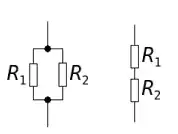
A better solution would be to treat R1 and the 2.475V source as the Thevenin equivalent of some resistor divider between the 5V supply and ground. It's funny, we usually apply Thevenin's theorem to simplify resistor dividers into their Thevenin equivalent of a single voltage source and single resistor, but here we need to do the opposite!

Like the last schematic, you need resistors to derive 2.475V from a 5V supply, but their equivalent "paralleled" value should be 10k, to keep the gain correct at about 3. That is:

$$ \begin{aligned} 5 \times \frac{R_4}{R_3 + R_4} &= 2.475 \\ \\ \frac{R_3}{R_4} &= \frac{5}{2.475} - 1 \\ \\ R_3 &= 1.02 \times R_4 \\ \\ \end{aligned} $$

Paralleled they should be equivalent to 10kΩ

$$ \begin{aligned} \frac{R_3R_4}{R_3+R_4} &= 10k \\ \\ \frac{1.02R_4R_4}{1.02R_4 + R_4} &= 10k \\ \\ \frac{1.02R_4}{2.02} &= 10k \\ \\ R_4 &= 19.8k\Omega \\ \\ R_3 &= 1.02 \times R_4 \\ \\ &= 20.2k\Omega \\ \\ \end{aligned} $$

So, the simplest solution I can think of, assuming you have a stable 5V supply, is:

schematic

simulate this circuit

Simon Fitch
  • 27,759
  • 2
  • 16
  • 87
2

Voltage scaler

You'll need a negative supply rail because the output swings to -5 V.

  • Once more, thanks a lot! Can I use TL074 instead without changing the resistors? Also can you confirm if I understand the process correctly: since for 1.65V change in the input I want 5V change in the output, I need Gain = 3.(03). Therefore, R3 and R4 are 33k and 100k, respectively. Since at 0V we want output equal to -5V and we will have only the bias voltage it needs to be 1.65V. Then since at 3.3V from the formula for voltage divider of 2 sources we see that we want V+ at 5 to be 2.48V. Then from the voltage divider and the input we find that R1=R2*3.03. Hence same resistors. – Ognyan Petkov Aug 16 '22 at 15:33
  • @OgnyanPetkov Yes, you have the ratio correct correct but a simplification is to say that the ratio = (total output swing)/(total input swing) = R1/R2 = R3/R4 = 10/3.3 = 3.0303. Another design simplification I use, for that configuration, is to say that the bottom of R1 should always be connected to the mid-range of the output signal (0 V) and the input to R4 should always be connected to the mid-range of the input signal (1.65 V). IC1a, the buffer, is required so that the 1.65 V generating potential divider isn't loaded by R4 & R3 which would change the 1.65 V reference voltage. –  Aug 16 '22 at 16:12
  • @OgnyanPetkov I would expect the circuit to still work with a TL074, I can't see any reason why it shouldn't. The TL074 is the quad version, TL072 is the dual version. –  Aug 16 '22 at 16:14
  • 2
    @OgnyanPetkov The reason I didn't use the Thevenin equivalent at the inverting input is that with the Thevenin equivalent it's not possible to filter out any hash and noise on the power rail which would be applied directly to the op amp's inverting input. By actually generating the 1.65 V reference and buffering it it's possible to filter the 1.65 V reference by placing that large capacitor, C1 across it. –  Aug 16 '22 at 16:38