3

Are pogo pins (e.g. this one) suited for 1 GHz?
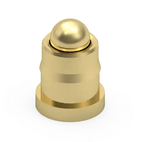
Pogo pin

user171780
  • 627
  • 6
  • 19
  • 1
    I see no showstopper. But consider that GHz is always differential, i.e. it can be only considered together with the return conductor. So at a minimum you need 2 such pins. But it could be difficult to control the line impedance with pins. Ideally the manufacturer provides impedance ratings for certain pin types at certain distances. – tobalt Aug 15 '22 at 09:28
  • Do you know of any application? For example, I know some Apple connectors use pogo pins but I cannot find if this is for DC power only, or also high speed data. – user171780 Aug 15 '22 at 09:39
  • 2
    CPU sockets use pins (not sure if pogo). A lot of them are IO..So HF is possible – tobalt Aug 15 '22 at 09:40
  • 2
    Is this for an RF application or a digital one at 1 GHz? And note that almost all RF applications/interfaces even into the multi-GHz range are really single ended. – SteveSh Aug 15 '22 at 11:45
  • 1
    Not digital, analog. I need to pass through this fast pulses with a spectrum between 200 MHz and 1-2 GHz. The source of such pulses is a small silicon device, and the idea is to connect it straight to the input of an integrated RF amplifier using one of these pogo pins. So the distance between the source and the amp would be about 3-5 millimeters. – user171780 Aug 15 '22 at 12:59
  • @SteveSh single-ended still needs two conductors at RF. With differential I just wanted to emphasize this fact. Both conductors must be laid out with well defined spacing. – tobalt Aug 15 '22 at 13:15
  • @user171780 - I would look for a pogo pin that's characterized at the frequencies, 200 MHz - 2 GHz that you're concerned about. S parameters are what you're looking for. – SteveSh Aug 15 '22 at 13:38

1 Answers1

4

I use similar short smt pogo pins for 30db RF amplifier test at 894.75MHz working very well, make sure UUT (Unit Under Test) is well grounded.

Without prior RF knowledge our first design used longer touch type, vs solder on, pogo pins and ended up with bad values and over running current. At the recommendation from our customer we redesigned with the shortest SMT pins we could find and works very well. Simple input Vcc and inject a signal/read gain using Rhode and Schwarz ZVH8 in S21 mode with 30dB attenuation on port 2(Cal>Other>Normalization, so we read back actual value). Of course alternative equipment can be used.

Good Luck!

user323418
  • 41
  • 2