3

Story

Get my hands on two Metabo (made in Germany) cordless DC battery powered hand drills previously thrown away because of..... the batteries, how sad. The overall construction is simple however pretty stiff and clever designed with quality components.... a keeper! "The Post Apocalyptic Inventor" aka TPAI made a video about making obsolete tools useful again. The solution is simple, use an external battery or PSU to power the tool by installing a connector. I did it a little different, used a different and more regular connector and install the connector on a different location. The result is actually equal to the TPAI version.

Metabo modded drill


Problem

At the first try, I notice that after starting the motor (huge inrush current anyway) it stops immediately (with some reverse turn shake feedback). Through the ventholes of the motor I noticed some huge sparks when the motor stops. This abrupt "kick out" behaviour is not very healthy for the switches, bearings, the gears and the brushes, possibly effecting the lifetime of the device. I have notice similar behaviour at other brands, only at high speeds and release the (speed controlled) trigger quickly. These ones has no electronic speed control, it is just on or off in selected direction.

When disconnect the power source (remove it), this problem does not occur and the motor slows down by friction and power loss.

After figuring out how it works (very clever designed in matter of simplicity of construction) I understand why.

Switches and config

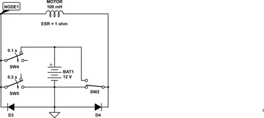
The motor is shorted (in feedback/generator state) when releasing the power trigger, because of the clever configuration of the two 2-state power on slash direction switches in parallel. However this results in a huge feedback current and build up coil voltage inside the motor. That is the reason why the brushes spark intens and the motor stops immediately after high speed rotations. To avoid feedback to the batteries this is good but can have some negative impact on other components because of the sparks and internal feedback force.


Question

Old & new design

  1. I have tried to design a new addon solution (mod) in the existing configuration. Cut the negative lead and added two diodes and a resistor. I am not a professional so I wonder if this is a plausible solution to slow down the decrease of speed and limit the feedback current/voltage inside the circuit. What do you think, it this okay?
  2. If this solution is plausible, why manufacturers do not apply this even at quality tools? To avoid the best quality? Wear is a selling point?
Codebeat
  • 1,317
  • 1
  • 11
  • 35
  • It won't work with the diodes as shown. If you reverse them, the battery current will flow through one or the other, and they will need to be able to handle high current (perhaps 20A) with minimal forward voltage drop. It might be better to install an RC snubber across the motor. – PStechPaul Aug 10 '22 at 05:40
  • @PStechPaul Hai Paul, thanks for the commen and idea. Updated the schematic, whoopsie. That is why I ask it first before trying and to get some ideas about it. The switch is rated 10A 250V. The voltage will be 12V so I calculated C = 1 / (12^2)*1 = 7uF and R = U/I = 1,2 Ohm. Am I right? – Codebeat Aug 10 '22 at 16:02
  • 1
    That is dynamic braking where when you remove the power the motor becomes a generator and the output of the generator is burnt up. Sometimes via resistors, in your case it appears they took the fast way and just shorted the motor terminals. I will assume the manufacturer knows what they are doing and this is what it was designed to do. – Gil Aug 10 '22 at 16:28
  • 1
    @PStechPaul Just think about your solution but it doesn't help in this case because when the motor is turned off the terminals of the motor are shorted by the two switches. If I want to use a RC snubber I have to use other switches. – Codebeat Aug 10 '22 at 17:13
  • @Gil Thanks for the comment. Aha, learned something new "dynamic braking", never heard of it. Okay, it is part of the design and maybe the cheapest way to do it however I don't like this behaviour, I want to change it because of wear/stress of components. – Codebeat Aug 10 '22 at 17:15
  • 1
    @Codebeat, I saw that after posting my comment. – PStechPaul Aug 10 '22 at 19:41

4 Answers4

2

schematic

simulate this circuit – Schematic created using CircuitLab

Figure 1. A pair of diodes can snub the motor when running in either direction.

The diodes will conduct only during transition of SW1 or SW2.


schematic

simulate this circuit

Figure 2. Simulation circuit.

enter image description here

Figure 3. Simulation results. Top: voltage at Node 1. Bottom: current traces.

  1. SW4 (representing the NO contact) opens at 0.1 s. Voltage rapidly swings negative.
  2. SW5 (representing the NC contact) closes at 0.2 s.
  3. D3 keeps the current running through the motor.
  4. The current through the NC contact decays from a low initial value to zero.
Transistor
  • 168,990
  • 12
  • 186
  • 385
  • Just looking at the circuit and I think D3 and D4 doesn't make sense because of S1 and S2. – Codebeat Aug 11 '22 at 14:10
  • About your current flow update..... You wrote that this the current flow after SW1 is released however in your schematic SW1 is removed and R1 is not used. This is very confusing. When SW1 was still there, like as in the previous schematic, the current does not go through D3 but the switch. In fact the same situation as before, not very useful. Or do I miss something inhere? – Codebeat Aug 11 '22 at 23:57
  • 1
    Simulate it in falstad and the whole circuit make no sense because of the configuration of the switches SW1 and SW2 in closed position. Actually you can see already the problem when you following the square with closed switches. It is a short circuit and all the other components has no effect. – Codebeat Aug 12 '22 at 01:16
  • @Codebeat - I think we were both partially incorrect. I had superfluous diodes and resistor but D3 and D4 are essential for my principle of operation. I know the switches short out the motor when both are in the NC position. The point I'm addressing is during the transfer between one contact breaking and the other making. See if the update fixes the problems. Thanks for the feedback. – Transistor Aug 12 '22 at 18:17
0

One possible solution would be to replace the diodes in your idea with NTC thermistor current surge devices. You can get them rated at 25 amps with an initial resistance of 2 ohms and resistance of 0.02 ohms at rated current. It would cause a delay before maximum current would be available. When the switch is turned off, the motor would see the 2 ohms of the cold thermistor, so it would experience a relatively slow braking at about 6 amps initially for a 12V battery.

PStechPaul
  • 7,195
  • 1
  • 7
  • 23
0

A inexpensive and relative simple solution for dynamic braking would be to place a low value in the braking circuit maybe in the 2 ohm range. This will increase the reliability as there is no semiconductors involved. When you release the switch the output voltage of the motor will rise very rapidly. initially the resistor will conduct a lot of current, as the pulse rapidly decays the current will reduce to zero. You can empirically determine what resistor you will need. As it is a pulse load, not steady state You can use a smaller resistor.

Gil
  • 4,951
  • 2
  • 12
  • 14
0

I like the idea with the two diodes and the break resistor. In this circuit I try to avoid the losses across the diodes using MOSFETs. This can only work, if at no time both switches are activated, but I assume this is impossible in this machine.

schematic

simulate this circuit – Schematic created using CircuitLab

  1. Activating one direction switch will enable the MOSFET on the opposite side. The low pass filters R4/C1 and R5/C2 should protect the gates from short voltage spikes, where ever they might come from.
  2. Releasing e.g. SW1 will activate the break resistor. There will be a short negative back EMF, that is clamped by the body diode of MOSFET M1 and the diode D2 can quickly tun off the negative path via M2.
  3. I added the diodes to be sure that the negative path is no longer conducting if the opposite switch is activated while the motor is still rotating. Probably not needed.
  4. C3 and C4 together with R1 form a snubber network to protect the contacts, this is more a question of EMI style.

I did not test this circuit, so there may be aspects I'm currently not aware of.

This sure would make the machine more expensive, I can understand why this is not implemented regulary.

Jens
  • 5,598
  • 2
  • 7
  • 28