Over the past weeks, I've been looking into an analog method of dividing 2 voltages such that V1/V2=Vout. I found many sources on Google using methods like log and antilog amplifiers or a multiplier, but every time I model one in Falstad or Multisim, I can't seem to get it to work as proclaimed. I only need one quadrant (inputs should range from 0 to 10 V or so), and accuracy isn't terribly important. Please keep in mind I understand just enough about electronics to understand how foolish and impractical this is; I just want to know if it's possible to do, and in all honesty I'll almost certainly use a dedicated chip for this if I'm ever ready to commit this to a breadboard.
Asked
Active
Viewed 381 times
0
Wrig Nine
- 3
- 4
-
Why not a conventional voltage divider composed of two resistors? https://en.m.wikipedia.org/wiki/Voltage_divider – user1850479 Aug 08 '22 at 02:33
-
@user1850479 I've seen about a million of those, but they unfortunately won't work because I want to divide one variable voltage by another variable voltage, rather than a variable by a constant. Unless there's some way to do it with voltage-controlled resistors, I just don't think that's what I'm looking for. – Wrig Nine Aug 08 '22 at 02:42
-
Using Spehro's circuit, if you make V1 or V5=1 V then you get what you want. For example making V1 = 1 V gives (1*V5)/V4 = V5/V4. – Aug 08 '22 at 04:44
3 Answers
2
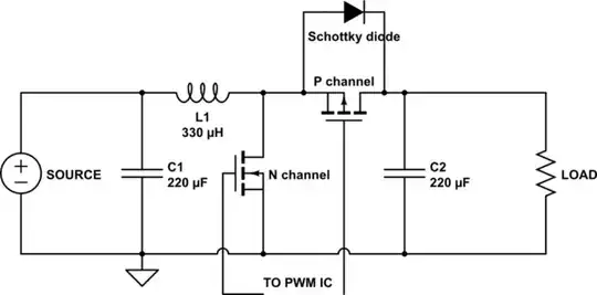
Here is a more-or-less practical circuit that does what you are asking. You can connect V5 to a reference voltage to scale the output so it does not saturate.
V1, V4, V5 must be > 0.

Relatively small op-amp offset voltages, resistor tolerances and differences in transistor matching or temperature can result in large output offset voltages with this kind of circuit. Diode-connected transistors are used because they have more ideal behavior than ordinary diodes.
It would be a good idea to parallel them with inverse diodes if you build this and if the minus rail is much more negative than -5V since the E-B junctions have a relatively low breakdown voltage.
Spehro Pefhany
- 376,485
- 21
- 320
- 842
-
An advantage of using transistors in that situation (over diodes) is that you can remove the error effect of the op amp's input offset voltage, but to realise that advantage you must connect the transistors' bases to actual ground. – Aug 08 '22 at 04:28
-
I was going to suggest an analog multiplier/divider IC like https://www.mouser.com/ProductDetail/Analog-Devices/AD534KHZ?qs=NmRFExCfTkEX75QH1A1nFw%3D%3D, but the cost is prohibitive. I think I have a few of these in my old stock from 30 years ago, so I might be rich! – PStechPaul Aug 08 '22 at 04:52
-
1@PStechPaul Yes, that's the classic way to do it- with a 4-quadrant multiplier chip like [AD633](https://www.analog.com/media/en/technical-documentation/data-sheets/AD633.pdf). They are not cheap, but the newer ones are fairly well trimmed. I think they typically use a translinear Gilbert cell architecture inside, which might be fun for OP to explore. Also used in popular RF mixer chips. – Spehro Pefhany Aug 08 '22 at 05:16
-
-
is the CB junctions worse in terms of ideality? If not, that could be used instead of EB junction for better reverse voltage rating. – tobalt Aug 08 '22 at 07:18
-
@tobalt I believe it is worse, which is why the configuration I showed is used. As to the solid-state physics-related reasons, I think jonk has looked into it, I have not. – Spehro Pefhany Aug 08 '22 at 07:37
-
1might have some new data for bc847/bc857 soonish, at least down to ~10 fA. But i remember seeing an old plot with many diodes and JFET/BJT diodes, where CB and EB looked similar. – tobalt Aug 08 '22 at 07:49
-
1I found the plot from my memory. It is reply #15 here: https://www.eevblog.com/forum/projects/forward-leakage-of-a-diode/ However, my memory was wrong in that both junctions aren't similar. EB is much more ideal, as you mentioned – tobalt Aug 08 '22 at 19:00
-
Hey Spehro, so I was presented the data for the BC857C. Both BE and BC follow perfect Schockley with ideality ~1. The lower limit for exponential I-V behavior is ~1pA (50mV) for BC and ~2pA (40mV) for BE. Though this is *not* because the junctions stop being ideal below this current, but because Schockley is no longer exponential below ~50ish mV and the junctions continue to follow Schockley. – tobalt Nov 14 '22 at 08:01
-
However, the Schockley behavior only really works for positive bias. For negative bias, current doesn't saturate as predicted by the equation, but appears to rise rather linearly in voltage (up to a few 100 mV considered here, even more beyond). So for this circuit, one would need to make sure that the BJT-diodes never leave the positive bias regime - even when using BC junctions. – tobalt Nov 14 '22 at 08:18
1
If you need a multiplier/divider that works at high frequency (like 250 MHz), you can get an IC that does that, but it costs about $26: https://www.mouser.com/datasheet/2/609/AD835-1502319.pdf
For much lower frequencies, up to several kHz, you might be able to use a ratiometric ADC and DAC.
And another option is to use a microcontroller with two simultaneous sampling ADCs, perform the computation in software, and provide an analog output using a DAC or PWM.
I found an obsolete MC1495 multiplier IC for about $6. You can use a multiplier to perform analog division:


Here is the internal circuit of the MC1495. Probably very similar to other such multipliers:

PStechPaul
- 7,195
- 1
- 7
- 23
1
As Sphero mentioned, a translinear Gilbert bipolar circuit could be the core of a divider. These use the current-to-voltage logarithmic/exponential relationship of transistor \$V_{be}\$ vs. \$I_c\$, plus the addition / loops-sum-to-zero of Kirchhoff's Voltage Law of \$V_{be}\$'s, to achieve multiplicative relationships between currents.
For example, we can configure four (identical) NPN transistors as shown:
simulate this circuit – Schematic created using CircuitLab
The simulation above is a working CircuitLab circuit simulation. Click it, run the DC Sweep simulation, and you'll get the following plot:

The output is on the y-axis. The first input is on the x-axis. The second input is the three different colored lines. It's a divider!
You can change the order of the DC Sweep simulation parameters to swap I1 and I2 order if you'd like to have the denominator be on the x-axis, instead of the numerator. Here's what that looks like:

This may look more like the \$y \propto \frac {1} {x}\$ shape that you're expecting to see from a divider, since we have the denominator on the x-axis.
How does it work?
In this configuration, the \$V_{be}\$'s of Q1 and Q2 add up to some voltage. By KVL, This voltage is equal to the sum of \$V_{be}\$'s of Q3 and Q4:
$$V_{be,Q1} + V_{be,Q2} = V_{be,Q3} + V_{be,Q4}$$
The translinear principle has some approximations (i.e. assume high/infinite transistor gain, so we can neglect all base currents) under which \$V_{be} \propto \log {I_c}\$. Since the addition of logarithms follows \$\log{a} + \log{b} = \log{a \cdot b}\$, we now have:
$$I_{c,Q1} \cdot I_{c,Q2} = I_{c,Q3} \cdot I_{c,Q4}$$
We'll call our output \$I_\text{out} = I_{c,Q4}\$, and we'll assume we have some fixed bias current \$I_\text{scale} = I_{c,Q2}\$. And we'll let current sources I1 and I2 be our inputs. So we have approximately:
$$I_\text{out} = I_\text{scale} \cdot \frac {I_1} {I_2}$$
Can it be made practical?
Your question was looking for voltage inputs and outputs -- not currents! It is possible to add a few op-amps and transistors and accomplish voltage-to-current conversion for the two inputs, plus current-to-voltage conversion for the output. For example:
This too is a working CircuitLab circuit simulation (though admittedly it is a pretty slow simulation). If you run it, you'll get:

The above plot has \$V_1\$ on the x-axis, and \$V_\text{out}\$ on the y-axis.
If you swap the order of the DC sweep parameters around, you'll see this:

Now we have has \$V_2\$ on the x-axis, and \$V_\text{out}\$ on the y-axis. From this you can see that \$V_1\$ is our numerator, and \$V_2\$ is our denominator. We can see some saturation behavior too.
This is all based on a lot of approximations! It's not an exact divider but may be good enough depending on your use case.
I'd bet that the various analog multiplier ICs being recommended in the comments here actually probably look a lot like this internally. :)
compumike
- 3,624
- 23
- 20