2

I have a 24 VDC 'signal' coming from the same line a solenoid is being supplied from. This signal comes from a PLC.

I have the need to take this signal and 'invert' it, so it can be used to drive another solenoid in a flip-flop fashion, i.e. when the first solenoid is off, the second (child) solenoid should be on, and vice-versa.

I've looked at using a simple NPN transistor, but am slightly confused as to how I would 'feed' the original 24 VDC into it and if I would need a further high-power transistor, to actually power the second solenoid.

I've also explored using an opto-coupler and feeding the original signal into it, but I would still need to invert the signal using a logic level 'inverter' chip, plus I would also need some kind of driver circuit to power the second solenoid.

This all seems to be rather complicated, just to invert the 24 VDC signal for use on another solenoid, so any advice would be very much appreciated.

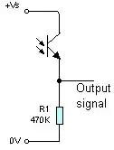
I've added a pseudo circuit layout, in which I could add a basic digital inverter.

The obvious other thing I could do is just use a PCB mount relay, but again this feels unnecessary for what it's doing and prone to failure.

ocrdu
  • 8,705
  • 21
  • 30
  • 42
  • Could you clarify what you mean when you say "signal"? Is this simply a voltage on two wires driving the solenoid? If yes, then do you have another wire that can provide power when solenoid is off? For example, if switching off is done by removing +24 from one wire then you need another 24V permanently available. If switching is done by disconnecting -24V (or GND) then you'd need permanently available ground from somewhere – Maple Aug 06 '22 at 21:39
  • Hi @Maple, yes I have the means to provide another 24V supply to the device, that was my intention. But to clarify, The original solenoid signal is coming from a PLC, I wish to 'invert' this, so when Sol A is on, Sol B is off and vice-versa. Hope this makes sense. – user3263740 Aug 06 '22 at 22:59
  • If that is the case, then you only need one NC relay connected in parallel with first solenoid. Just one part instead of all those "inverting circuits", and wiring is trivial. Relays are very reliable, especially reed, SSR or vacuum sealed types. Properly sized relay will draw little additional power and last forever. Another option is connecting DPST relay instead of original solenoid and use it to switch power between two solenoids. – Maple Aug 06 '22 at 23:41
  • Relays are mechanical and have known failure modes, however if properly selected and implemented the working life can be quite long - in the order of 100,000's of operations. A relay could probably rival the mechanical life of your solenoid. They can take a fair amount of abuse and survive. Personally, I'd just use a relay unless you have other constraints that preclude using them. – Kartman Aug 06 '22 at 23:53
  • @Kartman, if *a relay could probably rival the mechanical life of your solenoid* by having the same MTBF, then the MTBF of the two together is halved. Add in the other solenoid and the MTBF together is reduced to a third. Meanwhile, a transistor, two resistors and a diode can do the relay's job with better volume and far better reliability, cost, noise etc. So a relay would be a poor choice over solid-state, whether these factors were inconsequential or not. The only relay advantage might be ease of wiring. – TonyM Aug 07 '22 at 07:50
  • @TonyM i was only suggesting pragmatism by using magnetism. – Kartman Aug 07 '22 at 11:00
  • @Kartman, if only there was a word for 'don't, whatever you do, use relays over a solid-state equivalent unless it's 1954 again, it's always worse' that rhymed with pragmatism, the world would be a lot better off :-) – TonyM Aug 07 '22 at 12:35
  • @TonyM By your logic the second solenoid must not be added at all, because it will double the chance of failure. You also ignoring the "R" in "SSR", implying that solid state devices are not relays. Now, regardless of how you call them, if MTBF of a system divided by 3 still leaves us with hundred years then I don't see a problem. That is what Kartman meant by "properly selected" relay – Maple Aug 07 '22 at 16:04
  • 1
    Honestly, Relay was the first option I considered, but if it was the option I'd wanted, I would have already designed it by now. I didn't like the idea of the mechanical and potential failure mechanism of using relays, when (I'd through), there should be a fairly straight forward electronic way of achieving the same thing. There was also the space element to the design, I'd hoped I could fit all this onto a small PCB for an in-line connecter, but the more answers I'm seeing, the more I'm thinking the component count is going to be large anyway (size of those parts might not be huge though). – user3263740 Aug 07 '22 at 20:17
  • @Maple, I can't see you're following the logic at all, though it's not mine in particular - maybe re-read the comment. Note *whether these factors are inconsequential or not*. Anyway, OP wants solid-state, rightly so, for all the good reasons. – TonyM Aug 07 '22 at 20:37

6 Answers6

1

If this signal can't drive the solenoid directly, you can invert it with an NPN or a power MOSFET. Ensure that you select an NPN with sufficient current capability.

You basically need to drive the base of the NPN with sufficient base current to saturate it -- calculate this as the solenoid current divided by 20. The base current will be (approx) 24 V/RBASE.

Connect the NPN's emitter to GND, and drive the solenoid between 24 V and the collector.

If you use a MOSFET, you will still need the diode, and you can drive the gate with 1k Ω from the signal, and an additional 470 Ω between gate and ground. This will limit the gate voltage to ~ 8 V.

You will need a diode to protect the NPN from inductive spikes when the solenoid turns off -- easiest way is to connect the diode 'backwards' across the solenoid.

If in fact the 24VDC signal can directly drive a solenoid, then just connect the solenoid between that signal and ground.

jp314
  • 18,395
  • 17
  • 46
  • Thanks JP314, I'm not sure what you mean with 'If in fact the 24VDC signal can directly drive a solenoid...' Yes the original signal can be used to power both solenoids, but I'm not sure I see how the circuit works as you describe. Are you saying, still use the NPN, but connect the second solenoid directly to the transistor? – user3263740 Aug 06 '22 at 21:36
  • Basically connect both solenoids in series across the supply. Connect the signal to the middle. When HIGH, the lower solenoid will be enabled; when LOW, the upper one. No need for any other components. – jp314 Aug 06 '22 at 21:49
  • Holy s**t...would this work! Could it be this simple. I just sketched it on paper and it just looks too simple. – user3263740 Aug 06 '22 at 23:03
  • Check with a single solenoid to 24 V When the signal is low it should be on, etc... – jp314 Aug 06 '22 at 23:11
  • 1
    I'm not sure about this. I feel like, it seems to work OK in one direction, but not in the other, unless you make some assumptions: such as, The PLC is switching on the low-side (which it almost certainly is) and that when you don't have the signal tied to 0V, it is rising to 24Vdc and not half the potential. The simulation needed a SPDT switch with one end tied to ground to work. I mean, I suppose it could just be a case of adding a pull-up resistors of some kind on each line (if I'm understanding correctly, of course), not the end of the work. GIF: https://pasteboard.co/QRRUXVuuJzJk.gif – user3263740 Aug 06 '22 at 23:58
  • See the edit in my answer :) – PStechPaul Aug 07 '22 at 00:48
0

One simple solution would be to use a resistor divider to drop the voltage to lower logic level and then use the digital inverter you mentioned. Here's a topic on the subject: How to invert a digital signal. And a suggested solution with an NPN transistor for inverting: BJT inverter

The inverted signal can then drive a transistor as a low side switch to the solenoid.

You are mentioning a PLC, so I assume an industrial environment that may have transients on the signals. Either the NPN base resistor or the resistor divider will provide some protection. Using a FET would be risky.

Ralph
  • 3,026
  • 1
  • 4
  • 22
  • If you use this to drive a solenoid, you need spike protection for the NPN. Typically a diode across the solenoid will work. Also you don't really need R1 – jp314 Aug 06 '22 at 21:24
  • I did think about this, as it's a very simple solution to get for 24VDC to 5VDC, but I would still then need to invert the signal and then provide a driver to the new solenoid (I was thinking of a ULN2003 type device, in the instance that I ended up using logic). I kind of thought doing this in industry was frowned upon? – user3263740 Aug 06 '22 at 21:38
  • I only illustrated the inverting part. You can connect a NPN transistor to Vo and R1 will be the base resistor and the latter transistor can then act as a "low side switch" (Good search term, if you are not familiar with it) for the solenoid. – Ralph Aug 06 '22 at 22:11
  • @jp314 Yes, a flyback diode should be added for the solenoid drive. R1 is needed to prevent a dead short on logic low. – Ralph Aug 06 '22 at 22:13
  • So a bit like this: https://pasteboard.co/pqbBwqDtzNai.png – user3263740 Aug 06 '22 at 22:40
  • Delete R1 -- don't short the collector to 24V. Not like the picture -- the collector is just connected to the solenoid (which is connected to +24 V) – jp314 Aug 06 '22 at 23:13
  • The picture in your link shows the original solenoid driven from a high side switch. And you are trying to drive the second solenoid through a 3000 ohm resistor, and then shorting out the LED that you seem to be using in place of the solenoids. You have not given the resistance of the solenoids, but they are probably much lower than 3000 ohms. I used 240 ohms in my simulation, for a current of 100 mA. – PStechPaul Aug 07 '22 at 21:31
  • The picture was only the inverting part, as the question was how to invert. I assume rest of the circuit was clear for the OP as he is already driving one solenoid and he didn't ask. And to be clear: The intention is not to drive the solenoid directly from Vo in the picture or through any resistors. – Ralph Aug 08 '22 at 08:45
  • Follow-Up on all this great info... Can I drive the base directly form the 24Vdc, with the appropriately sized resistor to limit current?, or do I need to drop down the voltage and if so, is it good practice to use a potential divider in a circuit like this....that would by far be the easiest option, if I can't use just a limiting relay? – user3263740 Aug 28 '22 at 21:31
  • Yes, you can put a series resistor to limit the current from 24 V. – Ralph Aug 29 '22 at 15:57
  • I recommend with playing around with LTSpice. You just need to draw the circuit and run a very basic DC or transient analysis. – Ralph Aug 29 '22 at 16:13
  • Coming back to this after a while and this solution will enable me to simplify my circuit massively. I've re-worked my circuit using an NPN on the input, the bit I'm struggling to work out the resistor values for this circuit with a 24Vdc input and an output that will need to trigger the input to a ULN2003(A). I currently have the Base as 20K and 30K on the Collector to limit to 0.8mA on the input. Any help greatly appreciated. – user3263740 Mar 17 '23 at 15:05
  • Please post the full circuit and describe the problem, sounds like the values are ok. While input is 0, current will flow through ULN2003, through 30k + 2k7 resistance and output current is limited to ~700 mA. – Ralph Mar 27 '23 at 10:34
0

If the first solenoid is grounded, and powered from a 24V signal, you can use a PNP transistor to drive the second solenoid from the 24V supply. A PMOS device would also work, if you adjust R1 and R2 to provide proper gate voltage.

24V solenoids simulation with PNP

If the drive voltage for the solenoid is push-pull, the two solenoids could be connected in series, as suggested above. But if the signal is open collector, a push-pull driver can be constructed as follows:

24V solenoids simulation with push-pull

Schottky diode D3 added to simulate open collector drive.

You might also be able to move solenoid L1 to replace R1, and eliminate Q1:

24V Solenoids simulation Invert NPN

PStechPaul
  • 7,195
  • 1
  • 7
  • 23
  • Thanks for the great examples. What do you mean by push-pull. I believe the output is open collector, but can confirm. Is there any configuration you'd recommend for keeping the component down to packaged IC devices? Part of me thinks, just using a divider, with discrete components after (an inverter and driver IC), might be best for space? – user3263740 Aug 07 '22 at 20:53
  • If the output is open collector, the third circuit would be simplest, and requires only a single NPN transistor. But the second solenoid would need to have one side grounded. If you want to have the second solenoid driven by another open collector, just add another NPN to GND with the base driven through a resistor to the emitter of the first NPN (Q2 in the simulation). There is no need for logic circuits unless you have another purpose other than operating the second solenoid. – PStechPaul Aug 07 '22 at 21:18
  • I suppose one piece of important information, is that this is for X6 secondary valves flip-flopped from the primary. I suppose this is why I was thinking that divider with inverter and driver IC's would be the simplest in terms of space and construction. – user3263740 Aug 08 '22 at 08:16
0

Option 1: NC relay in parallel to original solenoid.

Option 2: SPDT relay instead of original solenoid.

schematic

simulate this circuit – Schematic created using CircuitLab

Maple
  • 11,755
  • 2
  • 20
  • 56
0

I will pick up your idea using an industrial opto coupler module.

If, and only if the coupler input current is far below the holding current of the first relay (RLY1) you can achieve the signal inversion by connecting the coupler input between +24 V and the PLC output. In this case the coupler receives an input signal if the PLC output is off but the current is too low to activate or hold RLY1.

The other constraint is, that the coupler output is rated for the required current of RLY2.

Having a snap in coupler module this is done in no time.

schematic

simulate this circuit – Schematic created using CircuitLab

Jens
  • 5,598
  • 2
  • 7
  • 28
-1

From the question I understand the "24V signal" is actually driving the solenoid. But you don't say if this signal is active high or active low.

If it is active high, then the solenoid is on when 24V is present, and you want to turn on the other solenoid when 24V is not present. If it is active low (and the driven solenoid is between +24V and this signal) then it's the opposite.

In the active high case, you can use the schematic on the right: a transistor to invert the signal, then a MOSFET to switch the second solenoid. If it is active low, then it's +24V when the solenoid is off, and that can drive the MOSFET directly to turn on the other solenoid.

enter image description here

bobflux
  • 70,433
  • 3
  • 83
  • 203
  • Did you add a short between the drain and 24 V by mistake? If the currents are high the high value gate resistors are going to cause stress on the FET. – Ralph Aug 06 '22 at 22:18
  • Yes totally by mistake. Corrected it. Resistor values: they're solenoids, they're not going to switch at tens of kilohertz, a bit of switching loss is better than lots of EMI. Values should be adjusted according to current, which is not mentioned in question. – bobflux Aug 06 '22 at 23:05