I am playing with a cascode op-amp design and I have problems judging its stability (schematic at the end of the post).
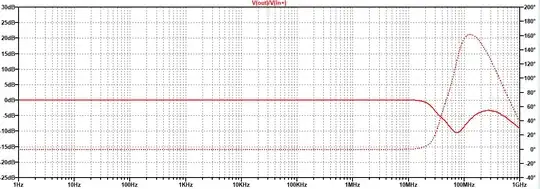
When I judge the DC or AC analyses, it all looks good. No peaking and good phase margin well beyond the unity gain point (~10 MHz ballpark).
However, in the time domain (.tran) analysis, the whole thing is oscillating, at about 1-10 MHz. Essentially, the current mirror is oscillating between fully on and fully off, with the current alternating between both input legs. I have tried changing several things, but the oscillation persists, only changes frequency slightly:
- component values
- inserting some
.optionssuch ascshuntorgmin - replacing the ideal elements with real elements
- reducing the gain on the current mirror and on the level shifter M3
- compensation capacitors
- setting the input voltage source to zero constantly
- replacing V4 with a current source and resistor
The only thing that remedied the oscillations in the time domain analysis, was to reduce abstol=1e-4. But as this is such a 'weak' convergence value, I think that it would rather mask issues instead of repair them.
Another remedy comes with the fix recommended by @James in comments, however, this seems to deteriorate the AC plots severely as seen below the schematic at the end.
Question
Does this mean that the below op-amp structure is by design not going to work? If so, why not?
If there is no fundamental flaw, do you have some suggestions what could be the issue?
AC plots before and after fix recommended by @James
The fix was to add a 100 pF miller cap to M3 and increase the closed loop gain to 10. The time domain sim becomes stable. But I would have thought, that the "fixed" version looks much worse in AC - with even negative phase at the point of 0 dB gain. Probably, the fix doesn't oscillate because the input bandwidth is restricted to before the danger zone by R5-C3.


