0

In my PCB, I am using 2 DC-DC power modules B0505S-1WR3 and B0512S-1WR3. The power module B0512S-1WR3 is working as expected with output voltage 12V when activated. But B0505S-1WR3 is having a problem, it is not giving any output when switched on. I tested it on 2 PCBs, and both yielded the same result.

The schematic and the PCB design are available at the following links.

Full project:

https://oshwlab.com/sigrama/centinela-tester-20211026_copy_copy_copy_copy_copy_copy_copy_copy_copy

Schematic:

https://easyeda.com/editor#id=6362cac3833c4c708b427543f0b94831

PCB:

https://easyeda.com/editor#id=cfa50c9e8d6349088ce558d5928b9370

I then removed the B0505S-1WR3 from the PCB to test this module separately. Connecting a 5VDC from a mobile charger to the input of the module without any capacitor, I could read 5.6VDC output from this module.

I can think of one of the following as the problem.

  1. There must be a short circuit at the output of the module in the PCB which I cannot find.
  2. The capacitors used along with the module are not the correct ones.

Please help me troubleshoot it. Thank you.

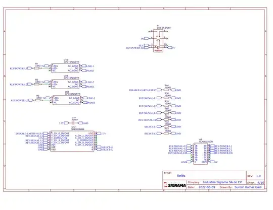
UPDATE: Schematic is given in the following pics.

Page 1

Page 2

Page 3

Page 4

Page 5

Page 6

Page 7

Page 8

Page 9

Page 10

UPDATE 2:

I observed that the result is the same when I reversed the polarity of capacitor C18. Also, the result didn't change when I removed the capacitor.

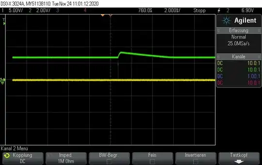
The output of the module looks like the following in the FLUKE 190-504 SCOPEMETER.
Output of the oscilloscope

SKGadi
  • 862
  • 3
  • 13
  • 1
    The schematic does not seem to show the DC-DC modules, and instead shows an ADC. The board layout is difficult to examine. It would be better to show images or links to PDF files. There almost certainly must be a short circuit on the board. – PStechPaul Jul 28 '22 at 22:59
  • @PStechPaul, it is available in the tab: PowerSupply. Also, I updated the link which takes you directly to the schematic. – SKGadi Jul 28 '22 at 23:33
  • 2
    if there's no voltage on the output pins of the 5V measure resistance there instead – Jasen Слава Україні Jul 29 '22 at 00:27
  • 2
    Looks like C18 is backward. – PStechPaul Jul 29 '22 at 02:48
  • 2
    Please edit your question to include the diagrams instead of relying on links that will disappear one day. – Finbarr Jul 29 '22 at 10:15
  • @Finbarr, Thank you for the suggestion, I updated the question. – SKGadi Aug 01 '22 at 15:10
  • @PStechPaul, wow, you are right. I didn't pay attention until now. I will reverse the Capacitor and check if that is the mistake. Thank you – SKGadi Aug 01 '22 at 15:10
  • @Jasen, I measured the resistance across `5V` out of the circuit and it shows `239 Ohms` – SKGadi Aug 01 '22 at 15:11
  • @PStechPaul, I tested by reversing the polarity of capacitor `C18` and also by removing the capacitor. The result is the same. I am updating the graph of output of the Module in the question. – SKGadi Aug 01 '22 at 22:55
  • 1
    Looks like something is drawing excess current or breaking down, like a zener. Try connecting a variable current limited power supply to the circuit and see what happens as you increase voltage. – PStechPaul Aug 02 '22 at 03:31
  • @PStechPaul, I don't have a good power source to test it. I will try to obtain one and test it. – SKGadi Aug 03 '22 at 13:03

0 Answers0