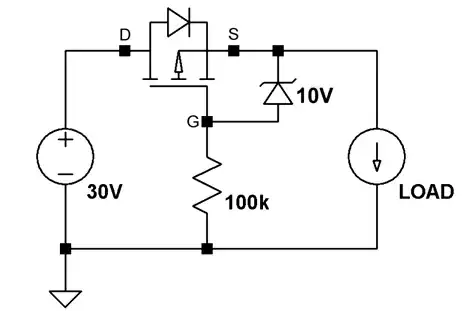
That type of circuit will not work as drawn because reverse voltage is not the same as reverse current protection. A true diode protects against both and but a simple PMOS circuit is not. A simple PMOS circuit plays games with the gate so that it behaves like a diode under some circumstances. A diode looks at the voltage between it's anode and cathode to decide whether to conduct. A simple PMOS circuit looks at the voltage between gate-source to decide whether to conduct. Under reverse-voltage the proper signal is applied to cause the PMOS to block but under reverse-current the signal applied causes the PMOS to conduct.
In your case, a supply on one side of the diode is trying to drive current backwards through it which means what you want is reverse current protection:
Reverse Voltage Protection the same as Reverse Current Blocking?
However, this additional circuitry will allow a PMOS to work as an ideal diode:
Understanding an 'ideal' diode made from a p-channel MOSFET and PNP transistors
However, you don't need something that fancy since your application does not require the same coverage of operation that a diode would provide. You can get away with a simpler circuit where the presence of the main power simply disconnects the battery when it is present:
How do I power a board multiple sources including USB without exceeding the capacitance limit on USB power?
It does not provide an ideal diode for the main supply, but it does for the battery which is the more important of the two as far as voltage drop is concerned.
