You could apply your AC signal to a current buffer. The output of the buffer would be a replica of the signal which you could process without removing power from the original AC signal itself. Pass the replica through a rectifier (or absolute-value circuit) and apply the result to a low-pass filter. If there's a signal, the voltage across the filter will be higher than if there isn't one. Let the output voltage from the filter a comparator. If the average voltage is high enough, the comparator will output a high signal. Apply that signal to an indicator light to show when there is a sufficiently large signal. You can lengthen the time constant of the filter to avoid having the light flash for short-duration signals.
Additional Information in Response to Your Comments
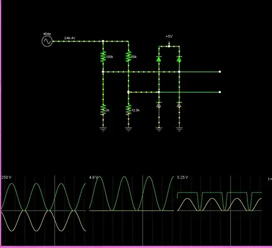
In the first stage of the partial schematic drawing above an Audio signal is applied to the non-inverting input of an operational amplifier. The very large voltage gain of the operational amplifier tends to make the output labeled Replica match the Audio input signal.
The next four stages of the circuit are identical. Each uses an operational amplifier in an inverting configuration and multiplies the voltage of its input by a factor of \$-10\$, achieved by my choice of the ratio of the feedback resistor to the input resistor. Plots of Audio, Replica, A1, and A2 appear here:

Note that the plot for A2 is actually shown as a negative of the signal of interest. This shows more clearly that all the signals are identical in shape. They only differ in magnitude and algebraic sign.
Here are the outputs of the later stages in this sequence:
Here you can see that A3 is 10 times as big as A2. I did not plot the negative of A3 as I did previously for A1. Signal A4 is 10 times as big as A3, but you can see here that the amplification is so great that amplifier U5's outputs have saturated at \$\pm15\text{ V}\$, the same as the voltage sources attached to its power supplies. This is not desirable for audio amplification, although for the purpose of seeing whether there is or is not an audio signal, it does not matter much. (Generally, though, driving amplifiers into saturation is inadvisable, if only because it takes time for the amplifier to get out of that state.) You also can see the absolute value of A4. The explanation of how this signal is created is next.
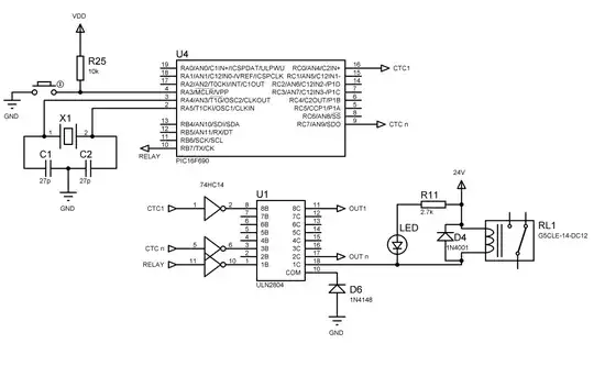
The additional signal processing is done by the circuit shown in this schematic drawing:
The first stage is constructed from two operational amplifiers. It computes the absolute value of the input. I took the circuit from this link:
Understanding absolute value circuit operation
which, in turn, took it from a Texas Instruments publication.
The next stage uses operational amplifier U8 to filter the result. For low frequencies the capacitor looks like an open circuit, so the operational amplifier simply inverts its input, giving the negative of the absolute value. For high frequencies, the capacitor looks more like a short circuit, and the operational amplifier tends to attenuate them. The overall effect is to give the negative average of the absolute value. By taking the absolute value, negative values of the audio input are made just as important as positive values for determining whether an audio signal is present or not. The average value of the absolute value will be non-zero if there is any audio power present.
The final stage applies this negative average to the inverting input of comparator U9. This device yields a high output if this input is lower than the \$-2~\text{V}\$ applied to the non-inverting input. Otherwise it yields a low value. The overall effect is to set the On_Off signal high if the Audio signal input has enough power in it—is strong enough—and to set it low otherwise. The results of the last few stages of the circuit are shown in these plots:
The filter output is more negative for stronger audio signals. When it is negative enough, the on_off signal goes high. While I don't show how this could be used to turn on a light here, suffice it to say that you could use it to turn on a transistor that would let current flow through, say, and LED to show that there is an audio signal present. The comparator can output negative output voltages. For the purpose of turning on an indicator light, this isn't necessary. Replacing the voltage at the comparator's negative input with a zero voltage (ground signal) would eliminate this trait, which might be objectionable in whatever follow-on circuit is used to power the indicator light.
I set the \$-2\text{ V}\$ comparator threshold pretty arbitrarily. Note that it is low enough to detect signals in the \$[0,10]\text{ ms}\$, \$[30,40]\text{ ms}\$, and \$[50,60]\text{ ms}\$ intervals, but not in the \$[20,30]\text{ ms}\$ interval, where there clearly is a weak audio signal present, and certainly not in the \$[10,20]\text{ ms}\$ and \$[40,50]\text{ ms}\$ intervals, where there is no audio signal.
One note about the audio signals. I used the LTspice simulator to synthesize them artificially. They include sums of sinusoids at 100 Hz, 1 kHz, and 10 kHz, all within the typical audible range of human beings, which runs from around 50 Hz to about 20 kHz.


