2

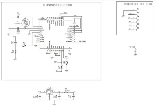
Can someone please help me understand this mystery data acquisition circuit. The circuit is both powered and digital data are communicated using a single wire. Current return is made through chassis. Special interface board must be used to operate gauges and acquire data to a PC or a master controller. Command word is sent to gauge by modulating cable line voltage, the gauge is responding by modulating line current.

Input voltage is between 8V and 24V. During programming its at -8V
enter image description here

enter image description here

FieryFire
  • 79
  • 3
  • 2
    A clever design, very classic. The drawing is a bit short on space so they resorted to using net labels and that obscures the functionality a bit. The basic building blocks are current mirrors, cascodes/common base stages, emitter followers, and current sources. What is your goal? Copy the circuit? Fix it? Interface with it? Let us know! – Kuba hasn't forgotten Monica Jul 21 '22 at 16:28
  • 1
    The [MCU Datasheet](https://datasheet.octopart.com/MSC1201Y3RHHT-Texas-Instruments-datasheet-148951.pdf) is key: "8051 CPU with 8kB Memory, 24-Bit ADC, Current DAC..." – rdtsc Jul 21 '22 at 16:33
  • Thank you Kuba. I am currently working with this data acquisition card. But i do not really understand the circuit. especially the the sheet with all the current mirrors, cascodes, current sources, etc. Could you please give a synopsis of what each part is doing? so i can study more about it. – FieryFire Jul 22 '22 at 06:12
  • If someone could help that would be great – FieryFire Jul 25 '22 at 08:03

0 Answers0