0

I wish to manufacture a flashing "signal light" which is activated when the light level is low.

It needs to operate on a 3 V battery.
The application is very cost sensitive so ICs such as LMC555 / 7555 don't suit the budget.

An NE555 costs about 20% of the above ICs but requires 5 volts and has current drain issues.

I need to add components like a photodiode or light dependant resistor (LDR) in the attached circuit to make the operation light sensitive so that it starts flashing after the sun sets.


Here is a circuit that I have experimented with. Can I use MOSFETs/FETs instead of BJT due to current drain?

Can anyone provide advice re improving this circuit, or a superior circuit that would meet my requirements

It uses flashing LED blinking, single color or non flashing LEDs. Where should I add the LDR?

The flash rate is 1.5 seconds, flash on time 30 milliseconds.

It flashes when the sun sets.

It uses two 1.5 volt D cell for a total of 3 volts.

The light should work for 20 days.


Modified circuitspedia diagram.

Single LED flasher.

On and off times settable by time constants of R1.C1 and R2.C2

enter image description here

Russell McMahon
  • 147,325
  • 18
  • 210
  • 386
  • Comments are not for extended discussion; this conversation has been [moved to chat](https://chat.stackexchange.com/rooms/137996/discussion-on-question-by-harshita-kapur-replacing-an-lmc555-or-an-7555-in-a-sig). – Voltage Spike Jul 23 '22 at 21:27
  • 3
    I have undeleted and reopened this question and edited it to make it more understandable (to some people) - hopefully i still says what you intended. || IMPORTANT This is a way for you to gain reputation points and have your ability to ask questions reinstated by the system. || SO Even if you no longer have this requirement please make EVERY effort to address points raised by people, to improve the question with any relevant details that are not in it. – Russell McMahon Apr 30 '23 at 13:05
  • 1
    Please add the answers to these questions to your question. Some of these are in the comments which were moved to chat. Most users will not see them there. || Q1 What is the desired on and off times? |Q2 If there are TWO LEDs then "1.5 seconds, flash on time 30 milliseconds." does not make sense. do you mean 1 LED only? |Q3 is flash time 30 mS on. 1.5 s off OR if not what do you want. | Q4 VERY IMPORTANT - what power or current do you want the LED to be on at when it is on? [A D cell is far larger than you probably need]. |Q5 Why D cells? – Russell McMahon Apr 30 '23 at 13:12
  • 3
    Did you note [this microcontroller](http://www.padauk.com.tw/en/product/show.aspx?num=4) suggested by @Spehro. It is available [here](https://www.lcsc.com/search?q=PMS150C) for $US0.08 in 10s and $US0.053 in 1000's. 1933 in stock :-) ! [datasheet here](http://www.padauk.com.tw/upload/doc/PMS15A,PMS150C%20datasheet_EN_V110_20230216.pdf) – Russell McMahon Apr 30 '23 at 13:26
  • @Harshita - your account is now NOT "blocked from asking". || You can now ask your new question: "... like how much a led draws in 20 msec if its rated at 20mamp. Wanted to strobe at peak." | If you do please provide as much relevant information as you can. Please try to make the question easily understandable and well formated. || An LED draws what the circuit design causes it to. Rise times of the actual LED are very short - in the nS range. If you drive it with a square wave voltage of say 5V and no current limit it will draw a large current. | I will be interested to see the question. – Russell McMahon Apr 30 '23 at 13:43
  • @RussellMcMahon - Thank you for undeleting, reopening, and improving this question, as I knew a circuit that might work handily, and have posted an answer. May you prosper! And thanks for serving the community. You are appreciated. – MicroservicesOnDDD Apr 30 '23 at 18:03
  • @RussellMcMahon Thanks, I saw that chip suggested by Spehro, works with 3.7 V Lithium battery . An issue again if we use 2 Lithium batteries in series as Low Dropout Voltage regulators are costly. – Harshita Kapur May 01 '23 at 04:02
  • @RussellMcMahon Just 1 led , other led can be ommitted. ON time should be 30- 100 msec, OFF time 1 sec , timings are approximate. Can we design using mosfets for low quiescent current. Uses 3V battery (1.5V x 3) , 5 mm led. – Harshita Kapur May 01 '23 at 04:12
  • From page 11 of the [datasheet](http://www.padauk.com.tw/upload/doc/PMS15A,PMS150C%20datasheet_EN_V110_20230216.pdf) that Spehro suggested you will see that the IC operates from 2 V to 5.5 V. This is comfortable outside the range of a LiIon cell (3-4.2V) or of two cheap carbon zinc batteries (sensibly 2.2 V to 3V) or of two Alkaline batteries (sensibly 2.2 V to 3.3V) – Russell McMahon May 01 '23 at 09:29
  • You have not answered Q4 . This is crucial to designing to work on given batteries for a given time. --> "Q4 VERY IMPORTANT - what power or current do you want the LED to be on at when it is on? "|| Q6: What colour is the LED? Your circuit will probably only drive a red LED at lower voltages and ONLY JUST drive a white LED with new batteries. || You did not answer Q5. || If you do not answer my questions, which are vital to the design, I MAY just ask again. Other people may downvote or vote to close. To keep questions alive you must take notice of user feedback and questions. – Russell McMahon May 01 '23 at 09:34
  • 1
    My 2 transistor low voltage flasher included in my answer [here](https://electronics.stackexchange.com/a/18006/3288) will probably do what you want. It MAY work for you on a single battery and will certainly work on two. Some "playing" would be required to get the required mix of brightness and inter-flash delay. – Russell McMahon May 01 '23 at 11:45
  • Q4 : its 5 mm led , operating current 20mA . All primary Colors and white. Some configurations use one AA cell , some use two AA cells in series , some use D cells 1 and 2 in series. Now design updating to Lithium cells as this question was closed 9 months ago. The former AA , D cells design still needed. – Harshita Kapur May 02 '23 at 02:39
  • @RussellMcMahon that circuit works but quiescent current is more . Iqc around 25 micro amperes is acceptable. – Harshita Kapur May 02 '23 at 02:58
  • 1
    @HarshitaKapur Your total requirement is still poorly defined, making providing the best possible advice hard. eg you say 20 mA LED current, duty cycle of 10% or less, night operation, 20 days battery life. At 12 hours a day x 20 mA at 10% I average is 20 x 12/24 x 10% = 1 mA. Over 20 days that's 20 mAh. = vastly less than the capacity of a D cell, or even an AA or AAA. AA alkaline cells at approx 3000 mAh capacity would operate for ABOUT 3000 days with no daytime current. Even at 1 mA quiescent that's 1500 days or about 4 years. || Can you provide a fuller task description in the question. – Russell McMahon May 02 '23 at 12:45
  • @HarshitaKapur Is this for "real world" manufacturing? What sort of volumes over what period? It would be interesting to know where this is going to be used. – Russell McMahon May 02 '23 at 12:46
  • @RussellMcMahon Not mass productiton but few hundreds as a hobby . It's day night blinking led – Harshita Kapur May 04 '23 at 02:12
  • @RussellMcMahon your led calculations are interesting . Assume 100 mA drawn into string of leds. ON time 200 msec , OFF time 1 sec . If we use NE555 with quiescent current of 3 -5 mA for NE555 for pulsing , what would be the life time , driven by 2 X 3.7 V cells , or 2 X 1.5 V cells ( some NE555 work on 3V ). Remember NE555 is always powered up during day and night – Harshita Kapur May 04 '23 at 02:22
  • Iavg per day = Iq24 + I1dl x H_dl/24 + Iloaded x H_night/24. || Iq24 - quiescent constant 24 hours. This - MAY be zero if Iqdl and I_loaded known. | Iqdl is Iq in daylight hours. | Iloaded is total current when LEDs on. Includes any Iq_night.| H_dl = hours in daylight mode. | H_night = hours in night mode. | So for H_night = 10, H_dl = 14, Iq_dl = 3ma, I_loaded 100 mA AT Vbat, ||| Iaverage = 3 ma x 14/24 + (100 + 3) x 10/24 = 1.75 mA (daytime Iq) + 43 mA (night time load + Iq) = 44.75 mA || ie nighttime load greatly predominates. If I_day is under say 10% I_night it can almost be ignored. – Russell McMahon May 04 '23 at 09:14

2 Answers2

2

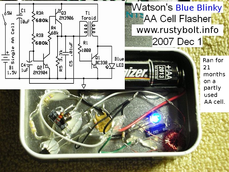
A Joule Thief Flasher from "Watson"

I am a fan of "Rusty Bolt", AKA "Watson A. Name", also AKA "Acme Fixer", who has been somewhat diligent in spelunking the Joule Thief space of Electrical Engineering which I have also studied somewhat. Watson made a circuit, a Joule Thief modification, which should do exactly what you want, and I present it here.

2011-12-02 Watson’s Blue Blinky Joule Thief Flasher

Here is a partial screen shot of the page, which tells you where to add the CdS photocell (under "Daylight Shutoff" - across the emitter-to-base of Q3):
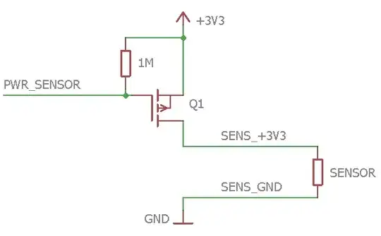
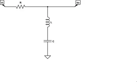
enter image description here

The Circuit

Here is the circuit itself:

enter image description here

My Verification

What now follows is my verification of the circuit in the very good free simulator LTSpice XVII, and the code itself for you to play with it:
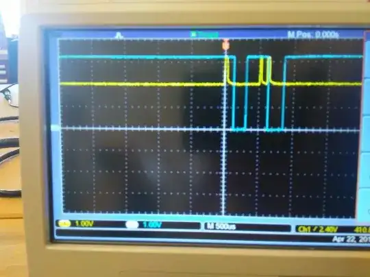
enter image description here

Flash Close-up

a zoom-in on one of the "flashes":

enter image description here

Measurement

and a measurement of the current going through the LED at the time of the flash (about 36mA):

enter image description here

The Code (LTSpice file):

You can also take this "LTSpice code" and paste it into an "*.asc" file, perhaps named something like "Watsons Blue Blinky.asc" on a Windows machine, in the LTSpice directory. Then you can open it and play with it there. Enjoy! (and if you meet Watson, please thank him for me! ;-)

Version 4
SHEET 1 952 680
WIRE -544 -192 -624 -192
WIRE -496 -192 -544 -192
WIRE -384 -192 -416 -192
WIRE -144 -192 -384 -192
WIRE 272 -192 -144 -192
WIRE -544 -160 -544 -192
WIRE -384 -160 -384 -192
WIRE -144 -160 -144 -192
WIRE -224 -112 -256 -112
WIRE -208 -112 -224 -112
WIRE 160 -112 32 -112
WIRE -544 -80 -544 -96
WIRE 160 -80 160 -112
WIRE 272 -80 272 -192
WIRE -384 -48 -384 -80
WIRE -256 -32 -256 -112
WIRE -624 32 -624 -192
WIRE -144 32 -144 -64
WIRE -32 32 -144 32
WIRE 32 32 32 -112
WIRE 32 32 -32 32
WIRE -32 64 -32 32
WIRE 272 64 272 0
WIRE 432 64 272 64
WIRE -384 80 -384 32
WIRE -384 80 -496 80
WIRE 160 80 160 0
WIRE 432 80 432 64
WIRE -256 128 -256 48
WIRE -624 144 -624 112
WIRE -496 144 -496 80
WIRE 272 160 272 64
WIRE -384 176 -384 80
WIRE -336 176 -384 176
WIRE -320 176 -336 176
WIRE -144 192 -144 32
WIRE 160 208 160 160
WIRE 192 208 160 208
WIRE 208 208 192 208
WIRE -624 320 -624 224
WIRE -256 320 -256 224
WIRE -256 320 -624 320
WIRE -144 320 -144 272
WIRE -144 320 -256 320
WIRE -32 320 -32 128
WIRE -32 320 -144 320
WIRE 272 320 272 256
WIRE 272 320 -32 320
WIRE 432 320 432 144
WIRE 432 320 272 320
WIRE -624 352 -624 320
WIRE -496 352 -496 208
WIRE 32 352 32 32
WIRE 32 352 -496 352
FLAG -624 352 0
FLAG -544 -80 0
FLAG -336 176 Q2b
FLAG 192 208 Q1b
FLAG -224 -112 Q3b
SYMBOL ind2 256 -96 R0
SYMATTR InstName L1
SYMATTR Value 100µH
SYMATTR Type ind
SYMATTR SpiceLine Rser=0.001 Rpar=0 Cpar=0
SYMBOL voltage -624 128 R0
WINDOW 3 30 172 Left 2
WINDOW 123 0 0 Left 2
WINDOW 39 0 0 Left 2
WINDOW 0 -68 57 Left 2
SYMATTR Value PULSE(0 1.5 0 100n 900n 5)
SYMATTR InstName V1
SYMBOL npn 208 160 R0
WINDOW 0 52 30 Left 2
WINDOW 3 53 62 Left 2
SYMATTR InstName Q1
SYMATTR Value BC337-25
SYMBOL LED 416 80 R0
WINDOW 0 -11 -34 Left 2
WINDOW 3 42 211 VLeft 2
SYMATTR InstName LED1
SYMATTR Value NSSWS108T
SYMBOL cap -560 -160 R0
WINDOW 0 -39 31 Left 2
WINDOW 3 39 32 Left 2
SYMATTR InstName C1
SYMATTR Value 10µ
SYMATTR SpiceLine V=6.3 Irms=0 Rser=0.002 Lser=0 mfg="TDK" pn="C4532X5ROJ47@M" type="X5R"
SYMBOL res -608 128 R180
WINDOW 0 36 76 Left 2
WINDOW 3 36 40 Left 2
SYMATTR InstName SW1
SYMATTR Value 10m
SYMBOL res -400 -176 R0
SYMATTR InstName R2
SYMATTR Value 680K
SYMBOL res -400 -64 R0
SYMATTR InstName R3
SYMATTR Value 680K
SYMBOL npn -320 128 R0
WINDOW 0 56 26 Left 2
WINDOW 3 51 58 Left 2
SYMATTR InstName Q2
SYMATTR Value 2N3904
SYMBOL cap -512 144 R0
SYMATTR InstName C4
SYMATTR Value 1µF
SYMBOL res -272 -48 R0
SYMATTR InstName R4
SYMATTR Value 68K
SYMBOL pnp -208 -64 M180
WINDOW 0 52 62 Left 2
WINDOW 3 50 32 Left 2
SYMATTR InstName Q3
SYMATTR Value 2N3906
SYMBOL ind2 176 16 R180
WINDOW 0 36 80 Left 2
WINDOW 3 36 40 Left 2
SYMATTR InstName L2
SYMATTR Value 100µH
SYMATTR Type ind
SYMATTR SpiceLine Rser=0.001 Rpar=0 Cpar=0
SYMBOL res 144 64 R0
SYMATTR InstName R1
SYMATTR Value 1K
SYMBOL cap -16 64 M0
SYMATTR InstName C5
SYMATTR Value 10nF
SYMBOL res -160 176 R0
SYMATTR InstName R5
SYMATTR Value 3.3k
SYMBOL res -512 -176 R270
WINDOW 0 32 56 VTop 2
WINDOW 3 0 56 VBottom 2
SYMATTR InstName R6
SYMATTR Value 1m
TEXT 136 -216 Left 2 !K1 L1 L2 0.95
TEXT 72 344 Left 2 !.tran 0 4s 0 1u startup
TEXT 360 88 Left 2 ;Blue\nLED
TEXT -120 144 Left 2 ;0.01µF
TEXT -600 -280 Left 2 ;circuit Watson's Blue Blinky Joule Thief by Rusty Bolt, AKA Watson A. Name, \nAKA Acme Fixer, circuit source: https://rustybolt.info/wordpress/?p=152

Disclaimer

I have not yet built this (but I'm about to). If anybody builds this, please let us know! Thanks.

MicroservicesOnDDD
  • 2,557
  • 1
  • 13
  • 48
  • 1
    Good low cost circuit with low quiescent current. "G" Search engine didn't show on first few pages, it was few weeks ago. – Harshita Kapur May 01 '23 at 05:09
  • @HarshitaKapur - Thanks. If you spelunk a little more on his site, he used another white LED instead of the Cadmium-Sulfide cell to turn off a blinker during daylight (because Cadmium is a hazardous substace and these photo cells can be hard to get). Here's the link: [2016-02-23 Joule Thief With Daylight Shutoff](https://rustybolt.info/wordpress/?p=11030). HTH. Enjoy! – MicroservicesOnDDD May 01 '23 at 19:57
  • Interesting circuit, but there is no way that costs less than an LMC555 circuit. The transformer alone probably costs more than the chip. – AnalogKid May 02 '23 at 13:47
  • @AnalogKid -- For typical industry, you're right. But toroid ferrites can be found cheaply, and the Joule Thief which is the core of this circuit, is typically custom-wound. If I were manufacturing a Joule Thief, I would try two cheap inductors and place them next to each other, or find a cheap toroid and add a secondary winding for the feedback (1K) side of the coupled-inductor. For more profit, it would be both less expensive and less labor to substitute the classic Joule Thief in this circuit with a Single-Inductor Joule Thief that should be easily found on the web. – MicroservicesOnDDD May 03 '23 at 04:41
1

It sounds like what you want is called a "Joule thief" circuit. This is an LED flash circuit that runs on very low voltage and current, such as what is available from an almost-dead battery. Many of these circuits use an inductor or small transformer in a blocking oscillator. There are many schematics for these circuits on the internet.

https://en.wikipedia.org/wiki/Joule_thief

https://en.wikipedia.org/wiki/Blocking_oscillator

AnalogKid
  • 16,865
  • 1
  • 13
  • 25
  • I have QX5252 IC for joulethief . But I need a different design altogether , like strobe pulse of 20 millisec every 1.7 seconds using low quiescent current mosfets and not transistors. Recently I have seen circuits using transistors for joulethief , – Harshita Kapur Jul 23 '22 at 14:20
  • @HarshitaKapur: [Metal oxide semiconductor field effect transistors (MOSFETs) are transistors.](https://en.wikipedia.org/wiki/MOSFET) Maybe you are trying to differentiate between MOSFETs and bipolar junction transistors (BJTs.) – JRE Jul 23 '22 at 14:31
  • @JRE ty, transistors are understood as general purpose bjt while mosfets are specifically mentioned as mosfets. – Harshita Kapur Jul 23 '22 at 14:45