2

I'm working on a simple single BJT transistor amplifier to amplify the output from an oscillator for use as a CW transmitter at 7 MHz.

I'm using an emitter follower to provide the power gain, and I'm trying to figure out how to match this to a 50 Ω antenna. I want to use an l-match but I don't know what the impedance at the output of the transistor is, so I don't know how to pick the component values.

I was thinking to just hook it up to a 50 Ω dummy load and iteratively pick values for the l-match trying to maximize the voltage across the 50 Ω load, but I don't think I'm going to be able to manually find optimal values for L and C. What is the correct way to go about doing this?

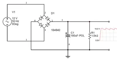
Here is the schematic:

enter image description here

ocrdu
  • 8,705
  • 21
  • 30
  • 42
goblinator
  • 31
  • 2
  • 2
    Can you provide a schematic of the intended emitter follower? It simplifys answering details. – Jens Jul 18 '22 at 03:45
  • I added the schematic. – goblinator Jul 18 '22 at 04:06
  • This might be helpful: https://electronics.stackexchange.com/questions/169675/how-to-measure-input-output-impedance-of-amplifiers-in-a-simulation – Lars Hankeln Jul 18 '22 at 04:28
  • I believe that in the broadcast context the impedance of the antenna might not be 50 (datasheet may have it), and they want you to add some inductors and capacitors before the antenna to make (antenna + components) equal 50. However, this only helps if your wires have a characteristic impedance of 50 - ordinary jumper wires don't. If the impedance of the antenna is already 50, and the wire is 50, then as far as antenna branch is concerned, you're good. No transmission line reflections from that branch. – ee_student Jul 18 '22 at 09:32
  • In my view, impedance matching in a 7 mhz case is not that important - the current will see far enough to recognize the antenna before it reaches it, so even if you don't match, serious reflections are unlikely. I'd be more concerned if the Emitter Follower can work at 7mhz, with a the transistor of your choice. You might need a transistor with a greater fT value. – ee_student Jul 18 '22 at 09:43
  • 1
    How much RF power are you designing for? The ~10mA DC emitter current only supports RF input up to about half-volt peak. Above that, you have (disastrous) 2nd-harmonic distortion, as current bottoms-out. So don't expect clean output above 2.5 mW. – glen_geek Jul 18 '22 at 12:01
  • Just a couple milliwatts, yes. Also going to LPF the output before the antenna. – goblinator Jul 18 '22 at 15:49
  • Could you also elaborate a little bit on the current bottoming out? In my spice simulation I see when my input signal is greater than .5 volts peak I have points where the collector current is 0, but I don't understand why, or how it relates to the emitter current. – goblinator Jul 18 '22 at 17:53
  • I think I understand now actually, a voltage change V at the base results in a V/(roughly 50 ohm) current change at the emitter, so if the input voltage change is too large it results in more than 10mA current change, putting the emitter current at 0 amps and putting the transistor into cutoff. – goblinator Jul 18 '22 at 18:04

1 Answers1

1

Suppose you have this circuit:

schematic

simulate this circuit – Schematic created using CircuitLab

The AC impedance of the base of the BJT is equal to :

$$\ \frac{V_{T}}{I_{E}} = \beta r_{e} $$

where $$I_{E}$$ is equal to the DC emitter current(ignore AC sources)

The input impedance of the emitter follower is simply $$ \beta (r_{e}+R_{E}) \left | \right |R_{b} $$

The output impedance of the emitter follower is $$ r_{e}\left | \right |R_{E}\left | \right |Z_{L}$$

In your case the input of the BJT is fed from the voltage divider of R1||R2:

schematic

simulate this circuit

So the only thing that changes is the input resistance which will be equal to $$R_{b1}\left | \right |R_{b2} \left | \right |\beta (r_{e}+R_{E})$$

In order maximum transfer of power to the antenna which is your load $$Z_{L} = r_{e} \left | \right |R_{E} $$ and from that point on all the tools needed to solve this problem have been given to you by me.

Miss Mulan
  • 1
  • 1
  • 5
  • 11
  • @TonyStewartEE75 The AC small signal analysis of the BJT gives Zin and Zout I think I have done it correctly... – Miss Mulan Jul 18 '22 at 04:35
  • Reconsider that Rout is driven by a current buffer of a voltage source that is AC coupled . So Rout must be the voltage source impedance (0) divided by . So you match it by adding 50 in series. However Re must also draw enough DC current to drive the peak AC current so it is also 50 ohms. – Tony Stewart EE75 Jul 18 '22 at 04:43
  • No it is incorrect. Do you understand it is not a current source like the collector? But a current amplified voltage input source for AC being 0 ohms with some loss due to re – Tony Stewart EE75 Jul 18 '22 at 04:45
  • "Do you understand it is not a current source like the collector?".What do you mean exactly? – Miss Mulan Jul 18 '22 at 04:56
  • I believe that for the Emitter Follower you'd put the test voltage between Emitter and ground. Hence the output impedance had to do with Re parallel to current going into the Base. Since current into the Base has a path to ground after passing the Base resistance, the whole of the impedance is Re || base resistance. – ee_student Jul 18 '22 at 09:17
  • More importantly, the goal is not to make the antenna impedance match the output impedance of the circuit. The goal is that if the characteristic wire impedance is 50 (they call impedance but in the transmission line context it has a special meaning - current through the wire doesn't behave as though it's passing through a 50 ohm resistor), while the antenna impedance is not 50, you can add some components before the antenna to transform the sum of (antenna + components) to 50 because that would match the transmission line before the antenna. – ee_student Jul 18 '22 at 09:27
  • 1
    Do you know how to verify impedance by testing with a series R to get 50 % loss? Try that on your favorite simulator. Yet ee_student is correct on the goal to match the antenna to the delay line impedance and it ok to use a lower impedance emitter as long as it is stable. – Tony Stewart EE75 Jul 18 '22 at 12:47