0

I'm designing a 40m radio. The schematic I'm using as reference uses a galvanometer ("S") for measuring the signal level. I'm trying to replace it with a sense resistor and an LM358 to read with an Arduino but I'm not sure what value resistor is best. As of now I'm between 100 Ω and 1 kΩ.

As per the docs:

The receive AGC circuit has an IF amplifier (Q3), a germanium diode detector (DC biased), and a drive amplifier (Q4) which has the "Strength-meter" in the emitter. Source
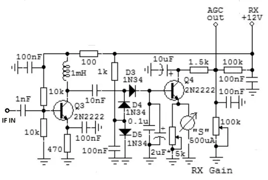
AGC Schematic

ocrdu
  • 8,705
  • 21
  • 30
  • 42
Arheisel
  • 3
  • 2
  • I think it is more in the direction of 10 kohm, just a guess – Jens Jul 09 '22 at 18:48
  • 1
    It's possible but that would make the 5k potentiometer an odd choice – Arheisel Jul 09 '22 at 18:53
  • More towards lower values. Probably 100 ohms. – JRE Jul 09 '22 at 19:05
  • Do you actually NEED the output labeled "AGC out"? If you do, you should try to match the galvo (as you have stated). If you don't, take the op-amp-amplifier-ckt's input from the emitter of Q4 directly, and set the pot to 5k (maximum). 5k is a good value here. A 358 is a good choice too; connect its + input to Q4's emitter, and connect its output+inverting inputs using 2 resistors in the usual configuration (values around 5k-100k are great) depending on how much gain you need. The Arduino probably wants 0-5V input for maximum range, and don't over-voltage-drive the Ard's input (5V max). – Atomique Jul 12 '22 at 20:27
  • The AGC Out is what I actually need to perform as close as possible to the design, It's what I put into my Cascade amplifiers at a different board. The S-Meter only needs to be somewhat precise as the Signal measurement in Ham is only S1 to S9 and is a very relative term (Each radio manufacturer decides what S1 and S9 corresponds to in dBm) – Arheisel Jul 29 '22 at 18:34

2 Answers2

1

The resistance of the microammeter should be fairly low.

This Simpson panel meter catalog has a 500 microampere meter with a resistance of 90 ohms:

enter image description here

The real resistance of the meter will probably vary depending on the manufacturer and model.

Since you want to measure the signal strength with an Arduino, I'd probably replace the meter with a 100 ohm resistor then use the AGC signal to feed the Arduino.

500 microamperes through 90 ohms only gives you a maximum of 45 millivolts - you'd have to amplify that considerably to use it with the Arduino.

The same 500 microamperes across the 1.5k resistor gives you 800 millivolts - just a little amplification with an LM358 would get you full scale for the Arduino ADC input (5V.)

JRE
  • 67,678
  • 8
  • 104
  • 179
0

The resistance of any analog current meter can vary dramatically depending on its sensitivity (which is usually a function of how rugged and how cheap it is -- expensive and fragile meters can be very sensitive, cheap rugged meters would be pretty insensitive).

I'd try to contact the author for the exact part number of the meter, or a guess at its resistance. Failing that I'd make a guess (as an educated guess, a \$5 \mathrm k\Omega\$ pot is about right -- in the authors opinion -- to be used to trim the meter's sensitivity. Unless the author only has \$5 \mathrm k\Omega\$ pots on hand, that indicates something between \$100 \Omega\$ and \$10 \mathrm k\Omega\$ to me).

Failing that, I'd just build the circuit with a fixed resistor there (or just the \$5 \mathrm k\Omega\$ pot) and I'd experiment with what values make the AGC work best.

TimWescott
  • 44,867
  • 1
  • 41
  • 104