0

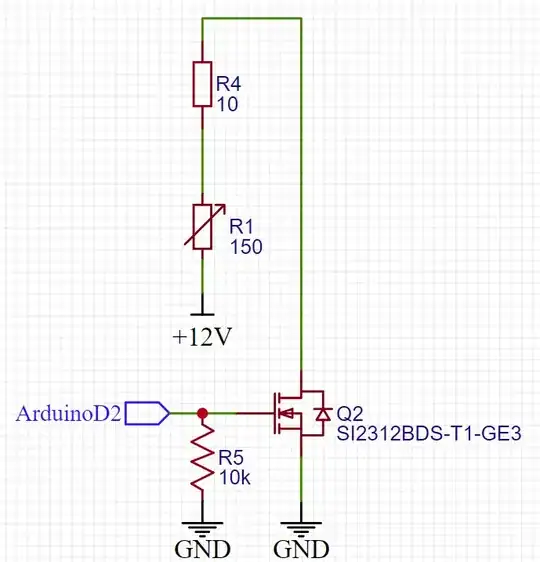
I am using an N-channel MOSFET to control 12 V for my voltage divider. The output voltage of the voltage divider is connected to a 24-bit ADC module (ADS1220) for calculating back the resistance of variable resistor R3 (actually a heater.)

I input 12 V and periodically turn the MOSFET on and off by giving Arduino Nano DigitalPin 5V and 0V. For the high state for the pin, the MOSFET is successfully opened and the DC power source for 12 V shows current flow but for the low state, the current is still detected, though not as high as in the high state. I think MOSFET is partially opened.

enter image description here

When I remove the 24-bit ADC module, the circuit works as my plan that when the DigitalPin is high, current flows, and when it is low the current is totally blocked.

enter image description here

I really cannot find the problem in my circuit as the only interrupting point of the ADC module and the MOSFET line is AI0 pin in the schematic.
JRE
  • 67,678
  • 8
  • 104
  • 179
djdlgl
  • 9
  • 1
  • 3
    Are you sure that ADC input can accept 12V? – Antonio51 Jul 08 '22 at 10:12
  • 2
    Looks like current flows not through closed MOSFET, but through internal protection diodes of ADC input. It could be burned already. – Vladimir Jul 08 '22 at 10:20
  • 1
    Your method is flawed. [Please consider this method](https://electronics.stackexchange.com/questions/64490/low-current-battery-monitoring/64491#64491) as it prevents your ADS1220 from being burned. Note also that the term "opened" in EE refers to a disconnection and not a connection as in pneumatics or hydraulics. – Andy aka Jul 08 '22 at 10:28
  • Thank you for the comments. Yes, ADC input tolerance is lower than 12V that is why I added voltage divider on the schematic and I didn't think about the current flow to ADC when the MOSFET is closed. I will follow @Andyaka 's method. Thank you for help! – djdlgl Jul 08 '22 at 11:27
  • You seem to be using the "water valve" convention, i.e. current flows when a transistor is "opened" and it does not when the transistor is "closed". **This is the opposite from English usage**. If you're using it, *edit your question* to correct it. The convention is of the transistor as a **switch**. When a switch (or transistor) is "open" no current flows, when it is "closed" then current flows. I find it much less confusing all around to say "on" and "off" -- pretty much everyone will take "transistor is on" to mean it's conducting current, and "transistor is off" to mean it's not. – TimWescott Jul 08 '22 at 14:52

1 Answers1

1

When you disconnect the MOSFET (by giving it a 0V input). Your DUT will float at 12 V from your 12 V PSU.

Therefore, the ADC pin will also be at 12 V which will be read as HIGH compared to your ADC reference.

If however, you are referring in your question to a current reading taken directly from your 12 V source. That would indeed indicate, that the FET is still slightly conducting. In this case, make sure that the FET Ground (i.e. the 12V PSU ground) and the Arduino ground are directly connected, to prevent potential Ground offsets. In particular, the two Grounds must not float with respect to each other.

But here comes the problem: If you connect the two grounds, then - when the FET is off - you will still get 12 V on your ADC pin which is beyond its maximum ratings and will destroy it. You must insert a current limiting resistor in your AIN0 line to prevent this. Current needs to stay below 10 mA, while you exceed VDD by 7 V. So you should insert at least 1kOhm there, better will be 10 kOhm.

enter image description here

Instead, use high-side switching (@Andy_aka posted an explanatory link in comments).

schematic

simulate this circuit – Schematic created using CircuitLab

tobalt
  • 18,646
  • 16
  • 73
  • Hello, I tested that my MOSFET is okay and as you said when I removed ADC module on my PCB and MOSFET turned off, 12 V was on R2 which is actually connected to ADC AI0 line. Therefore, I came out with an idea. I am going to move the voltage divider and ADS1220 line to Source side of MOSFET. Then, when MOSFET is off, whole 12V will be blocked and when it is on, by voltage divider ADS can get the value. Is it worthy? – djdlgl Jul 08 '22 at 10:55
  • That won't work, as you would then need ~15 V on the gate to turn it on fully. But you are on to something. You can use the N-MOSFET to control a P-MOSFET which will work as a high-side switch. – tobalt Jul 08 '22 at 10:59
  • First of all, thank you very much for the solution. According to my understanding, I can still use same NMOS and for PMOS, I need to use Vth at least 10 V and VDS = 20 V max right? – djdlgl Jul 08 '22 at 11:16
  • 1
    Ah! Wrong clarification. Vgs should be at least +-12 V – djdlgl Jul 08 '22 at 11:23
  • @djdlgl Yes PMOS gate-source voltage will be 0 V or -12 V, so it needs to tolerate up to 12 V. If you add another 100k resistor above M1, you reduce the gate voltage swing of M2 to 0 and -6V. With such a resistor you can adapt the circuit for use with smaller max. V_GS P-MOSFETs. But most of the beefier ones will anyway tolerate up to 20 V. – tobalt Jul 08 '22 at 12:14
  • Thank you very much for your clear illustration. Will adopt this circuit! – djdlgl Jul 08 '22 at 14:56