1

I'm really hoping someone can help me with this project. I've been trying everything I can to get this to work.

I have a project that senses current flowing via a current transformer (2000:1 20A max) and then controls a servo when the current turns on or off. These are hooked up to wood working machines, so they are on the higher current draw. The signal is passed to an ADS1115 with a gain set to GAIN_ONE.

All my devices are working fine on table saws, miter saws, routers, etc. Machines that draw 15A and will run continuously for long periods of time without any issues. The one machine that seems to always break my device is my drum sander, which does draw more power than other tools (20A). Everytime my device breaks, it's the arduino that fails (I think the voltage regulator breaks) and the ADS1115. Everything else on the board is fine. I've tried just resoldering a new board, reusing a board that I know works on other machines, but it still eventually fails.

The board doesn't fail right away... it's like 15 minutes of running that the board just dies. And given that it's only on this machine, I feel like it's something with my current transformer circuit. So below are my trials to fix this.

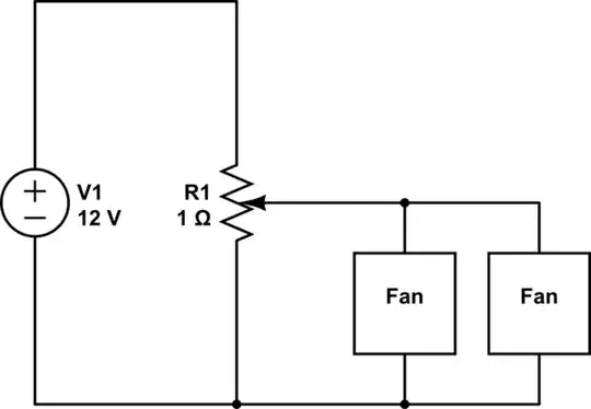
Here is my initial version that is working on all my other machines.

Initial version

When that failed, I tried changing my burden resistor to 100 ohms. That also failed.

I asked on reddit, and they suggested the burden resistor should be directly connected to the current transformer, so I tried that:

Inline Burden

That still eventually died. So then next, I tried to with a diode rectifier circuit:

Rectifier

That also died eventually. So I'm at a loss. Any help or suggestions would be greatly appreciated!
Neel
  • 11
  • 1
  • 2
    Did you measure the peak voltage at the analog input A0? I think, the current transformer may provide more than 5V and lifts the supply voltage via the internal ESD protection diodes to dangerous levels. Put a resistor >= 10 kohm between input A0 and the rectifier output. – Jens Jul 05 '22 at 19:25
  • I don't have an oscilloscope, so I wasn't able to measure it. Putting a resistor between the Burden resistor and A0 would change the voltage though, wouldn't it? A0 is measuring the voltage across the burden resistor, so adding a 10k resistor would dramatically change that voltage, right? – Neel Jul 05 '22 at 19:56
  • No damatic change: The input resistance of A0 is around 3 Mohm, you will not see a difference of some µV across the 10 kohm. – Jens Jul 05 '22 at 20:22
  • By the way: How is your I2C bus working without pullup resistors? Are the internal pullup resistors of the WEMOS strong enough? (This is not related to the problem, just curious) – Jens Jul 05 '22 at 20:29
  • I believe the pull-up resistors are strong enough... I mean they are working just fine on all my other devices. Though the ADS1115 breakout board that I'm using looks like it has a 10K pullup resistor on the I2C pins, so perhaps that's how it's working. – Neel Jul 05 '22 at 20:51

1 Answers1

0

Why did you insert diodes in CT sensor?
These could modify the reading of "exact" voltage.

The burden resistor is also too big ... Begin with a low value ~ 20 Ohm ...
And if the voltage input to ADC is too big, use an attenuator (2 resistors).
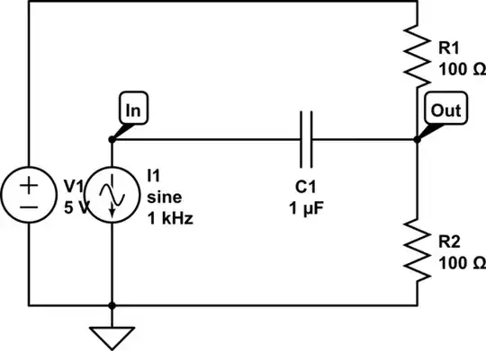
One must use a circuit with polarization at the middle bias point (3.3V or 5V /2) ... see my answer ...

From this : Measuring 230VAC 50Hz mains (EU) voltage with Arduino

And this : https://openenergymonitor.github.io/forum-archive/node/156.html

enter image description here

Just choose the components adequately.

Antonio51
  • 11,004
  • 1
  • 7
  • 20
  • The diodes are to avoid any negative current which the ADS1115 does not handle. I can try a smaller burden resistor though and see if that works. – Neel Jul 05 '22 at 19:24
  • 1
    With diodes, the CT can not work correctly ... – Antonio51 Jul 05 '22 at 19:30
  • I'm not sure I follow this. The circuit you gave is using a voltage divider to offset the negative voltage by 2.5v. In my circuit, I'm using a diode to stop the negative voltage from flowing and therefore I'm only reading the positive side of the current. Why does this fail for current transformers? – Neel Jul 05 '22 at 19:38
  • You also said I need a smaller burden resistor so the peaks are 1/2 of the voltage. That makes sense in your circuit where you are offsetting the current via your voltage divider. I don't need the bottom half of the current, which is why I'm just using a diode to drop that part and only read the positive side. – Neel Jul 05 '22 at 19:42